-
We can see light (in the sense of
visible light
to which the human eye is sensitive), of course---in fact, it
is all we do see.
- Beginning an Explanation of Light:
First, the term light can be used for either visible light or electromagnetic radiation (EMR).
The latter is the general class into which visible light falls.
Hereafter, we'll usually use EMR for clarity when talking about EMR.
What is EMR?
The short answer is electromagnetic radiation (EMR) is a traveling, self-propagating, transverse wave state IN the electromagnetic field which is everywhere always in all spacetime. This what is one says when being very exact.
But there is the old IN/IS dichotomy explicated in the figure below (local link / general link: electromagnetic_field_everywhere_always.html).
- An Example of Transverse Waves:
For an example of a transverse wave, see the animation in the figure below (local link / general link: transverse_waves.html).
- Mechanical Waves:
EMR waves require NO transmission medium in order to exist. They propagate in vacuum.
This makes them distinct from mechanical waves such as waves on a string and sound waves.
For mechanical waves, the medium oscillates in some way.
For waves on a string, it is the string that oscillates. For an illustration of standing waves on a string, see the animation in the figure below (local link / general link: standing_waves.html).
The animation in the figure below (local link / general link: standing_waves_sound.html) illustrates sound waves in a standing waves case.
- Electromagnetic Waves in Media and Vacuum:
EMR waves do propagate in media, of course, as well as in in the vacuum. They do interact with the media as they propagate through and cause it to oscillate in some sense and this slows them down (see subsection Light Speed in Media below).
What oscillates in EMR waves in vacuum? It is the electromagnetic field that oscillates---which can cause an ancillary oscillation in any medium too.
Note, in modern physics (to be specific in quantum field theory) is NO inert emptiness. It has active properties including the everywhere, eternal electromagnetic field---but we will skirt quantum field theory.
- The Energy of Electromagnetic Fields and Electromagnetic Radiation (EMR):
Electromagnetic fields (meaning particular electromagnetic field states) have an associated energy, and so EMR is also an energy flow.
Note, one can say simply that electromagnetic fields have energy.
The adjective "associated" in this context means a particular kind of energy which is the energy of electromagnetic fields.
There is an exact formula for the energy density of electromagnetic fields calculated from characteristics of the electromagnetic fields (see electric field energy and magnetic field energy). We will NOT describe this formula, but one can see it is pretty simple actually:
energy density = εE**2/2 + B**2/(2μ) ,
where E is the electric field magnitude at a point, B is the magnetic field magnitude at the point, and ε and μ are constants. The formula gives the energy density at the point.Similarly, kinetic energy is the energy associated with the motion of body and is calculated from the formula (that you probably saw in high school)
KE = (1/2)mv**2 ,
where m is the body mass and v is the body speed. The mass and velocity are characteristics of the body and its state.- Electromagnetic Radiation (EMR) Energy Conversions:
Any form of energy can be converted into any other form of energy which is one reason why all energy is energy.
Recall, the short definition of energy given in the insert below (local link / general link: energy_explication.html).
For example, sunlight is absorbed by a body---like your body---and becomes heat energy. The reverse process happens too. Bodies always convert heat energy into EMR. You only notice this when the bodies are hot enough to emit visible light. We discuss this emission process in IAL 7: Spectra: Blackbody Radiation.
The transformation of energy from sunlight and further transformations to power the biosphere are illustrated in the figure below (local link / general link: energy_transformation.html).
- Photons:
We described EMR as a wave, but it also has a particle nature.
The EMR particle is called a photon.
The dual nature of light and also of massive particles (particles with rest mass: most importantly electrons, protons, and neutrons) is called the wave-particle duality.
Microscopic particles really have only one nature.
The wave-particle duality arises from the two aspects that quantum mechanical particles have.
It's NOT easy to explain wave-particle duality without getting into the details of quantum mechanics---NOT even then really.
The figure below (local link / general link: qm_wave_particle_duality.html) gives a bit of an explanation of the wave-particle duality.
In fact, one needs both the wave and photon pictures to understand EMR---and actually all of microscopic physics.
We will mostly use the wave picture of EMR, but occasionally allude to the photon picture and look at it in a bit more detail below in the section Photons.
- An Example of Transverse Waves:
Light provides with information about the world. For example, about Big Sur: see the figure below (local link / general link: pfeiffer_beach.html).
And light provides
energy---as, for example,
the Crookes radiometer demonstrates---it's
a somewhat exotic example: see the figure below
(local link /
general link: crookes_radiometer.html).
But what we see doesn't tell us all about light.
So we need some explanation. In fact, the explanation goes on and on throughout this lecture and the next one IAL 7: Spectra.
-
EMR
is important because it is the means that nature has to
send information and energy over large distances and send it quickly.
EMR brings us energy from the Sun to heat the Earth and power the biosphere. See Biosphere videos below (local link / general link: biosphere_videos.html).
EMR
carries information from distant stars and
galaxies and from
the close in time to the Big Bang.
See the figure below
(local link /
general link: infinity_eternity_2b.html).
EOF
We take up the subject of the universe and the multiverse in IAL 30: Cosmology.
-
In this section, we consider, the vacuum light speed---
the fastest speed
at which information or energy can travel with speed measured at ONE POINT
relative to a local inertial frame---and this
speed is
invariant: i.e., it is
always exactly the same---which leads to a paradox
we go into below
in subsection A
Direct Implication of the Invariance Principle: The Relativity Paradox.
- Special Relativity and the
Fastest Physical Speed:
Albert Einstein's (1879--1955) theory of special relativity (published 1905) is a true theory of mechanics (which includes motion) and electromagnetism in the weak gravity field limit and a scale size much less than the observable universe (where curved space might be a consideration) and given that certain tricky cases in quantum mechanics need special explanations. To deal with strong gravity (like near black holes) and the whole observable universe, you need Einstein's general relativity (GR) (which is essentially a theory of gravity and motion under gravity). We consider general relativity in IAL 25: Black Holes and IAL 30: Cosmology. To deal with the tricky cases in quantum mechanics, one needs quantum mechanics. We will NOT consider those tricky cases, except briefly in subsection Qualifications About the Vacuum Light Speed as the Fastest Physical Speed.
One can say---and yours truly does say---that special relativity is an emergent theory that is exactly true in the limit specified by the limitations just specified above.
-
Question: In special relativity,
the vacuum light speed is:
- the fastest physical speed.
- equal to the speed of sound in air.
Answer 1 is right.We discuss the latter feature below in subsection The Vacuum Light Speed Invariance and the former below that in subsection How Do We Know that the Vacuum Light Speed is the Fastest Physical Speed?
The vacuum light speed (standard symbol c) is
c = 2.99792458*10**8 m/s (exact by definition) ≅ 3*10**8 m/s = 3*10**5 km/s ≅ 1 ft/ns .
The figure below (local link / general link: light_speed_earth_moon.html) illustrates the vacuum light speed.- Vacuum Light Speed Value:
As aforesaid vacuum light speed is inertial-frame invariant (and see again subsection The Vacuum Light Speed Invariance below).
So nature has given us an exact standard speed and international metrology decided to take advantage of this by defining it to be exactly given by vacuum light speed c = 2.99792458*10**8 m/s.
The particular choice of the trailing decimal fraction is for historical consistency.
Since nature has given us a universal speed standard, but NOT a universal length standard, the modern meter is defined in terms of the vacuum light speed and the modern second:
1 meter = c * [(1/299792458) s] is the modern definition of the meter.
So in the modern world, we use a standard speed to define the standard length rather than a standard length to define a standard speed.
Why are there NO standard lengths in nature to exploit? NO macroscopic scale objects are ever exactly identical. They must differ at the microscopic scale (i.e., the atomic scale) in an uncontrollable way at least.
Note, quantum mechanics dictates that all unperturbed atoms of the same species are absolutely identical, but we CANNOT use those at all as length standards for the macroscopic scale world NOR even for the microscopic scale world since atoms do NOT have sharply defined edges---they are fuzzy little balls.
- The Vacuum Light Speed Invariance:
How can we be sure that the vacuum light speed is absolutely invariant?
Two reasons:
- The Principle of Invariant Light Speed:
The principle of invariant light speed is the aforesaid absolute invariance of the vacuum light speed relative all inertial frame observers.
It is one of the two basic axioms from which special relativity is derived. Yours truly calls it the invariance principle for short.
Because the invariance principle is a basic axiom of special relativity, all special relativity effects depend on it.
Now special relativity has never failed an experimental test. Thus, indirectly, the invariance principle has been super-well verified.
In fact, a lot of axioms/results in modern physics are verified like the invariance principle, NOT just by direct testing, but by the verification of the theory of which they form a part.
If any part of a tightly connected theory is wrong, then everything in the theory is probably wrong---and we would know it---the theory and all that depends on it would fall apart like a house of cards with almost any single card removed without great care.
See a house of cards illustrated in the figure below (local link / general link: house_of_cards.html).
- The Principle of Invariant Light Speed Has Been Directly Verified:
All experiments capable of detecting variation in vacuum light speed find NO variation: i.e., they find invariance. So the invariance principle is directly verified by experiment.
The most famous of the experiments verifying the invariance principle is the Michelson-Morley experiment (1887) which was the first to make people think seriously about the invariance of vacuum light speed. The Michelson-Morley experiment (1887) is explicated in the figure below (local link / general link: michelson_morley_aether.html).
- The Principle of Invariant Light Speed Has Been Directly Verified:
- How Do We Know that the Vacuum Light Speed is the Fastest Physical Speed?
Three reasons:
- Reason 1 for the Fastest Physical Speed:
No faster physical speed has ever been observed which suggests there is none.
- Reason 2 for the Fastest Physical Speed:
Special relativity implies that faster than vacuum light speed travel relative to a local inertial frame gives time travel to the past.
Time travel to the past has NEVER been observed in nature NOR in experiment and leads to paradoxes that have NO unique resolution.
So Einstein ruled out physical speeds faster than the vacuum light speed in special relativity and NO observations have ever ruled them in.
It's disappointing to scifi fans, but nature needs NOT backward time travel. Forward time travel is NOT only allowed, but special relativity guarantees it. We will discuss forward time travel below in subsection The Twin Paradox.
Note, tricky superluminal effects in quantum mechanics trickily evade paradoxes and do NOT give time travel to the past in any ordinary sense.
Note also, to undisappoint scifi fans a tiny bit, general relativity does open the door a crack to the possibility time travel to the past, but most people think that possibility is NOT real. We discuss it a bit more in subsection The Twin Paradox.
- Reason 3 for the Fastest Physical Speed:
There is such a thing rest mass which is possessed by massive particles (e.g., protons, neutrons, and electrons), but NOT by massless particles of which the overwhelmingly prime example is the photon.
Special relativity dictates that massive particles take infinite energy to accelerate to the vacuum light speed. So they CANNOT be accelerated to the vacuum light speed and this is experimentally verified so far by particle accelerators among other ways.
On the other hand, massless particles have NO rest mass and special relativity dictates that they must move at the vacuum light speed always when in vacuum.
In fact, rest mass is a form of energy that massive particles have just by being able to exist at rest in an inertial frame.
The amount of energy in rest mass is determined by the only physics formula everyone knows: E=mc**2 which we explicate in a DIGRESSION in the figure below (local link / general link: e_mc2.html).
- Reason 2 for the Fastest Physical Speed:
- Light Speed in Media:
As everyone knows the speed of light in media is less than in vacuum.
Some cases of light speed in media are illustrated in the figure below (local link / general link: light_speed_in_media.html).
The short answer is light interacts with the media.
At the microscopic scale between atoms, light still moves at the vacuum light speed---or nearly so---see Qualification: lateral structure effects below in subsection Qualifications About the Vacuum Light Speed as the Fastest Physical Speed.
-
Question: Remember those
4th of July
fireworks. You've seen
jillions of them.
So to an observer at fireworks displays,
the sight and sound of an explosion are:
- simultaneous.
- in order sight then sound.
- in order sound then sight.
Answer 2 is right.As aforesaid, remember those endless 4th of July fireworks displays---John Philip Sousa (1854--1932), The Stars and Stripes Forever (1896): da da da da da da da da da, etc.
You see and then you hear since the speed of light in air is nearly the vacuum light speed which is much much faster than sound speed which in air at sea level at 20°C is about 343 m/s (Wikipedia: Speed of sound: Tables). Usually, you are at least 300 meters from the explosions, and so the sound delay is at least a second. So it seems as if you are watching a film with the picture and sound NOT synchronized properly. In fact, if you heard explosions in films from where the camera stood, there would often be a sound delay. It's just a convention of film language that sight and sound are simultaneous.
See Fireworks/drone art videos below (local link / general link: fireworks_drone_art_videos.html).
- Qualifications About the Vacuum Light Speed as the Fastest Physical Speed:
Actually, one must qualify the statement that the vacuum light speed is the highest possible physical speed/velocity with 5 qualifications:
- Qualification: geometrical velocities:
First, as aforesaid at the beginning of this section,
the expression "physical velocity" has a special meaning in this context.
It means the velocity at which information and energy
travel with speed measured at ONE POINT relative
to a local inertial frame of reference.
We elaborate on "physical velocity" and its opposite
geometrical velocity
below in subsection
Geometrical Velocities.
- Qualification: recession velocities: Second, velocities between inertial frames can exceed the vacuum light speed by arbitrary amounts. In fact, the comoving frames of the expanding universe (which are inertial frames and here we include approximate comoving frames) sufficiently far apart do have relative velocities exceeding the vacuum light speed. These relative velocities are called recession velocities. We take up recession velocities in IAL 30: Cosmology. A key point to reiterate is that NO information or energy travels with speed measured at ONE POINT relative to a comoving frame faster than the vacuum light speed, and so NEITHER we NOR the universe can do superluminal signaling. Light signals propagating through the expanding universe just move at the vacuum light speed relative to every comoving frame they are passing through.
- Qualification: wormholes: Third, general relativity predicts wormholes which are, among other things, shortcuts between two points in spacetime. Traveling through a wormhole would move you superluminally between those two points as seen from the outside. However, at every point in the trip through the wormhole, you would be moving at less than the vacuum light speed (or equal to it if you were a photon) relative to your local inertial frame (see Wikipedia: Wormhole: Faster-than-light travel). Note, it is NOT known if wormholes actually exist. Though a solution of general relativity, there may be NO process to create them in the actual universe. Also they may be forbidden by quantum gravity, the hypothetical fundamental theory of gravity to which general relativity is the macroscopic limit: i.e., it is an emergent theory of gravity.
- Qualification: quantum mechanical superluminal effects: Fourth, in quantum mechanics, there are tricky cases where one may speak of superluminal physical effects: i.e., there are quantum mechanical superluminal effects. But those tricky cases manage to avoid any paradoxes and forbid us from any superluminal signaling in principle. We tend to believe all this because quantum mechanics is the best verified of physics theories despite its seemingly eternal philosophical mysteries. It's all too much for us to expand on here.
- Qualification: lateral structure effects: Fifth, even light in a vacuum travels at less than vacuum light speed if the light beam has lateral structure: i.e., is NOT exactly in the form of plane waves (see J.R. Sambles, 2015, Structured Photons Take it Slow, Science, 347, 828). This lateral-structure effect is usually due to interactions with matter (e.g., with the walls of a pipe a light ray is propagating down). The lateral-structure effect is quantum mechanical (see J.R. Sambles, 2015, Structured Photons Take it Slow, Science, 347, 828) and is immensely small and can be only measured in extreme cases. So for virtually all purposes, the vacuum light speed is invariant in inertial frames. Another way of saying the same thing is that the true vacuum light speed is an ideal limit that is effectively reached in most cases. So we will NOT mention the lateral-structure effect again, but one must remember it as an actual effect.
- Qualification: recession velocities: Second, velocities between inertial frames can exceed the vacuum light speed by arbitrary amounts. In fact, the comoving frames of the expanding universe (which are inertial frames and here we include approximate comoving frames) sufficiently far apart do have relative velocities exceeding the vacuum light speed. These relative velocities are called recession velocities. We take up recession velocities in IAL 30: Cosmology. A key point to reiterate is that NO information or energy travels with speed measured at ONE POINT relative to a comoving frame faster than the vacuum light speed, and so NEITHER we NOR the universe can do superluminal signaling. Light signals propagating through the expanding universe just move at the vacuum light speed relative to every comoving frame they are passing through.
We will on Qualification: geometrical velocities just below in subsection Geometrical Velocities because its really easy to understand and just part of everyday life.
- Geometrical Velocities:
As aforesaid, the vacuum light speed is the highest physical speed---the fastest physical speed.
To clarify FASTEST PHYSICAL SPEED all over again all over again: we mean that NO information or energy can travel faster than this with speed measured at ONE POINT relative to a local inertial frame including those local inertial frames set up using inertial forces. Of course, we can should add if necessary the qualification about the tricky quantum mechanical superluminal effects we mentioned above in Qualifications About the Vacuum Light Speed as the Fastest Physical Speed.
The figure below (local link / general link: light_speed_earth_moon.html) illustrates the vacuum light speed again.
When such velocities occur, they do NOT convey information from one place to another.
For example, turn on two flashlights pointed in opposite directions. You would judge the relative velocity of the two beam heads to be 2c---and you would be right---but that is a geometrical velocity since NO information or energy is traveling at greater than the vacuum light speed with speed measured at ONE POINT relative to a local inertial frame.
-
Note, your determination of
2c
is based on a measurement at TWO POINTS
relative to a local
inertial frame.
Also note you are NOT finding the speed of one beam head relative to the other's "rest frame". In special relativity calculation that would lead to a relative velocity of c.
"Rest frame" is in quotation marks because talking about a light's rest frame requires some tricky qualifications.
In fact, it is the Earth that rotates with respect to the observable universe in its center-of-mass inertial frames, NOT the rest of the observable universe: see the figure below (local link / general link: /celestial_sphere_rotating.html). It is in this reference frame that local photons travel at the vacuum light speed.
- A Direct Implication of the Invariance Principle: The Relativity Paradox:
The direct implication of the invariance principle is actually itself when you think about.
All observers in any relative motion must measure the same vacuum light speed for a light beam.
Now I know what you are thinking: this conflicts with our ordinary understanding of RELATIVITY in regard to relative velocity. There is a RELATIVITY PARADOX
But there is no RELATIVITY PARADOX for the sound speed for instance for non-relativistic velocities at least. The sound speed you measure depends on your speed relative to the sound medium. In fact, you can move at the sound speed in air (meaning sound speed relative to air) in a jet and you could watch sound waves at rest if they were NOT invisible.
Watching water waves at rest is even easier. You can just walk along beside them in a swimming pool.
See the animation of water waves the figure below (local link / general link: water_waves.html).
The dependence of time flow rate on reference frame is called time dilation.
The RELATIVITY PARADOX is further explicated in the figure below (local link / general link: relativity_light.html).
- Time Dilation:
Time dilation (which is a main factor in solving the RELATIVITY PARADOX) is the relativistic effect that people usually find most mind-blowing---but it's quite real.
Time literally flows at different rates in different inertial frames. Inside an inertial frame time seems to flow normally, but in comparing different inertial frames the effect becomes noticeable.
But in everyday life, the time dilation is NOT noticeable because the relative velocites between inertial frames are too small.
We explicate time dilation in the subsections below.
- Moving Clocks Run Slow:
"Moving clocks run slow." is a mnemonic for one manifestation of time dilation.
The mnemonic can be expanded to be less pithy, but more specific: "A single clock observed moving relative to an inertial frame runs slow relative multiple clocks at rest in the inertial frame if they are spread out in space and relative to a single clock at rest in the inertial frame if the moving clock is accelerated."
We explicate this manifestation in the figure below (local link / general link: time_dilation_moving_clocks.html).
- The Twin Paradox:
Another manifestion of time dilation is the twin paradox which arises with accelerated motions. We explicate the twin paradox in the figure below (local link / general link: time_dilation_twin_paradox.html).
- Further Explication on Time Dilation with Accelerated Motions:
Further explication on time dilation with accelerated motions is given in the figure below (local link / general link: time_dilation_animation.html).
-
Note, yours truly emphasizes "ONE POINT" above since
it is key part of the description.
However, yours truly (like everyone else) does NOT
always say at "ONE POINT" because it is implied by context.
Note, "local inertial frame" means right where the measurement is done, not some remote inertial frame.
"Local" is a somewhat elastic term in physics. It can mean right where the measurment is done or near where the measurement is done in some sense which if you are being exact must be specified. However, people often let the meaning of "local" be set by context as we usually do for words with multiple meanings.
To clarify FASTEST PHYSICAL SPEED all over again: we mean that NO physical information can propagate faster with speed measured at ONE POINT relative to a local inertial frame, including those local inertial frames set up using inertial forces. Note, by local inertial frame, one means an inertial frame in which the light signal is traveling when its speed is being measured---NOT a remote inertial frame.
Of course, the fact that the vacuum light speed is the fastest physical speed is an aspect of special relativity, and so we must dive a bit into that subject. Special relativity is taken up in more detail in IAL 25: Black Holes: Special Relativity.
-
Group Activity:
Form groups of 2 or 3---NOT more---and tackle Homework 6 problems 2--6 on electromagnetic radiation (EMR).
Discuss each problem and come to a group answer.
Let's work for 5 or so minutes.
The winners get chocolates.
See Solutions 6.
-
In this section, go into a bit more detail on the
electromagnetic field.
- The Short Version:
This section gets a bit verbose.
So here is a short description of the electromagnetic field to keep in mind as we scroll along.
The electromagnetic field is a vector field that is the cause of the electromagnetic force.
It's everywhere in space and time.
It's modified by electric charge.
Particular electromagnetic field states which can be called electromagnetic fields are caused by particular arrangements and movements of electric charge and by creation by other electromagnetic fields.
Self-propagating electromagnetic fields (with NO electric charge needed for propagation) are electromagnetic radiation (EMR).
OK, now verbosity.
- What is EMR Made of?
As aforesaid in above subsection Beginning an Explanation of Light, electromagnetic radiation (EMR) is a self-propagating electromagnetic field.
Pure electric fields and magnetic field CANNOT self-propagate individually---just a basic fact of electromagnetism.
However, the electric field and the magnetic field are NOT actually distinct things though they look that in many contexts. They are both manifestations of ONE THING, the electromagnetic field.
To explicate to their ONE THINGNESS, note, an electric field is caused by a static electric charge and a magnetic field by moving electric charge. But if you move with a electric charge, you only observe only an electric field. So electric fields and magnetic fields mix their identities depending on the motion of an observer.
A self-propagating electromagnetic field (i.e., EMR) is a bit different in that a time-varying electric field creates a time-varying magnetic field which creates a time-varying electric field and so on. The electric fields and magnetic fields create each other to paraphrase Jack Nicholson (1937--). No electric charge is present where the self-propagation occurs though it is present at the creation and destruction of EMR (see below section Electromagnetic Radiation: Creation and Destruction).
Note, the electromagnetic field is a fundamental entity---it CANNOT be explained by something else---it is a "just so story".
Electric fields and magnetic fields are, respectively, the causes of, respectively, the electric force and magnetic force which are both felt by electric charge. Collectively, those forces are called the electromagnetic force. The situation is simplest if there is only static electric charge in a single inertial frame. Then there is only the electric force acts. If you have relatively moving electric charge, the description of the relative amounts of electric force and magnetic force can become complex depending on the case.
- What Are Fields Anyway?
In physics, fields are quantities that have value at every point in space and time or at least some region of space and time.
A field with only a real number value at every point in space and time is a scalar field. Examples are density, pressure, and temperature.
The electromagnetic field is, in fact, a vector field: at every point in space and time, it has have a magnitude and a direction.
One can think of little arrows attached to every point in space.
Note, while the vectors of a vector field point in SPACE SPACE, their extent is in their own abstract space---except for position vectors which extend in SPACE SPACE.
The directions of the electromagnetic field determine the directions electromagnetic force. The electric force is parallel to the electric field and the magnetic force is perpendicular to the magnetic field---which makes the magnetic force rather tricky.
Another example of a vector field is the velocity distribution of a moving fluid.
Yet another example of a vector field is the gravitational field which is the cause of gravity (i.e., the gravitational force). The gravitational field is usually given the symbol g⃗ (where the over-arrow means vector or by boldface).
Vector fields are further explicated in the figure below (local link / general link: vector_field.html).
- The Electromagnetic Field Real: Reading Only:
The electromagnetic field is a real thing, a real physical object.
It also can't be explained as something else---it is a fundamental entity---a just so.
You many wonder if it is a real thing since we usually just notice the forces between electric charges in what one ordinarily thinks of as electrical and magnetic events.
But, yes, it is a real thing.
There are 2 obvious ways to know this.
- One Way:
For one thing, changes in the electric force and magnetic force between electric charges are NOT communicated instantly when electric charges move or are accelerated. There is a finite propagation time.
The most obvious example of this finite propagation time is EMR.
EMR can propagate across the observable universe: propagating long after its source has been destroyed and long before its sink has come into existence.
- An Another Way:
For another thing, the electromagnetic field has an associated energy density---as we know for many reasons---one of those being that EMR transports energy.
- but has no mass density obviously.
- and thus has a mass density as we know from E=mc**2.
- but has negative mass density.
Question: The electromagnetic field has an energy density,
Answer 2 is right.Also recall the explication of E=mc**2 given in the figure above (local link / general link: e_mc2.html). From that explication, it is understandable that the electromagnetic field has mass, but NOT rest mass. Objects with rest mass CANNOT move at the vacuum light speed.
- An Another Way:
- Electric Charge:
Electric charge is a fundamental property of matter that comes in two flavors: positive charge and negative charge---which names were chosen by none other than Benjamin Franklin (1706--1790)---see the figure below (local link / general link: benjamin_franklin.html).
However, electric charge also causes electromagnetic fields as one of its basic properties.
Static electric charge causes electric fields and moving electric charge causes magnetic fields.
Since uniform motion is relative (with respect to inertial frames in both Newtonian physics and relativistic physics), the description of the electromagnetic field as either electric field and magnetic field must depend on relative motion---and which is why they are both manifestations of the same thing, the electromagnetic field.
Self-propagating electromagnetic fields (i.e., EMR) require more explanation which we give below in section Electromagnetic Radiation: Creation and Destruction.
Note EMR since it is a self-propagating electromagnetic field, does NOT need electric charge except for initiation. It can self-propagate across the universe.
- Field Lines:
For field lines in general, see the figure below (local link / general link: vector_field_field_lines.html).
For a very simple case of an electric field and a magnetic field represented by field lines, see the figure below (local link / general link: em_field_lines.html).
- Electric and Magnetic Fields and Forces in Everyday Life:
Electric fields and magnetic fields and their forces are actually ubiquitous in everyday life---as well as throughout the universe.
For example, electric generators and electric motors use them both.
Then there are those things you stick on your fridge---fridge magnets.
At the microscopic scale, electric fields in atoms and molecules and between them give materials their structure: i.e., they hold us together.
- What is EMR Made of?
-
Group Activity:
Form groups of 2 or 3---NOT more---and tackle Homework 6 problems 2--6 on electromagnetic radiation (EMR).
Discuss each problem and come to a group answer.
Let's work for 5 or so minutes.
The winners get chocolates.
See Solutions 6.
-
How do you create and destroy EMR?
- Microscopic Transitions:
If you make an electric charge undergo a transition in an atom or a molecules, the charge will emit EMR.
-
We'll discuss transitions later in
IAL 7: Spectra.
But, in brief, a transition
is a change in the internal energy state of an atom or molecule or solid.
But in most everyday phenomena, we only notice photons en masse, and so don't notice the particle nature usually---just as we don't notice that water is made of molecules of H_2O.
The reverse process happens too. A photon is absorbed to cause the reverse transition of an emission transition.
-
Can a human detect a single
photon?
No.
The retina does respond to a single photon, but neural filters suppress the signal.
For conscious psychophysical response, one needs 5 to 9 photons arriving in less than 100 ms = 0.1 s (see Can a Human See a Single Photon?, Philip Gibbs, 1996).
One could only notice so few photons with the eye adapted to very dark conditions.
They look like fuzzy little balls as illustrated by the actual image of atoms shown the figure below (local link / general link: atom_gold.html).
- Acceleration of Electric Charge:
A related process to transitions is the acceleration of electric charge.
For example, an alternating current (AC) in a conductor will generate radio waves (a form of EMR).
The reverse processes happens too: EMR can be absorbed by electric charges causing the electric charges to accelerate. This is how radio waves generate a current in a radio receiver.
The generation of radio waves by alternating current (AC) is illuatrated in the animation in the figure below (local link / general link: radio_wave_emission.html).
- Acceleration of Electric Charge:
With electric charge.
How does electric charge create and destroy EMR?
There are two ways as seen from the macroscopic scale, but which at a deeper level are really just one way.
The two ways are explicated below in subsections Microscopic Transitions and Acceleration of Electric Charge:
After creation and before destruction, EMR is a traveling electromagnetic field in the sense that it is independent of source and sink.
EMR can self-propagate across this room, from the Sun to the Earth, and across the observable universe.
Recall EMR is self-propagating electromagnetic field.
-
We argued in section Electric and Magnetic Fields that
the electromagnetic field is a real physical thing.
A main piece of evidence for it reality the ability of EMR to propagate across the observable universe.
If an electromagnetic field can propagate across the universe and travel long after it's source is destroyed and long before its sink is created, then one has to conclude that electromagnetic fields are as real as anything is real.
-
What does EMR look like?
Well, you should know since it's all you ever see.
But what you see is your psychophysical response which is NOT much like the mathematical description of physics.
-
Actually,
human vision
does NOT directly sense the
wave
nature of EMR.
The counts of photons
by the various
photoreceptor cells
(rod cells,
cone cells,
intrinsically
photosensitive retinal ganglion cells)
give rise to color vision
(see Wikipedia:
Photoreceptor cell: Photosensitivity).
From another perspective the frequency of visible light (fiducial range 0.4--0.7 μm) is of order 6*10**14 Hz (i.e., 6*10**14 cycles per second: see below section Electromagnetic Radiation Wavelength and Frequency), but neural oscillations (i.e., brainwaves) (which are electrical signal communications in the brain: the "speed of thought") are in the range 8--150 Hz (Wikipedia: Neural oscillations: Overview). Our brains are NOT nearly tracking the up-and-down oscillations of visible light (fiducial range 0.4--0.7 μm). Our photoreceptor cells transform (in a complex way) the high frequency of visible light (fiducial range 0.4--0.7 μm) into the low high frequency of neural oscillations.
-
Like all wave phenomena,
EMR can be characterized by
wavelength
or, alternatively, by frequency.
- The Relationship Between
Wavelength and Frequency:
To understand the relationship between wavelength and frequency consider a light wave cycle (i.e., a spatial pattern that repeats over and over again) propagating to the right:
        Time 1:  The wave cycle is just starting
          to pass point A moving at speed
          vacuum light speed c.

              __________
             |          |
                        |__________|

                                   A

              ---------- λ ---------

             The length of the wave or cycle is the wavelength
             which universally symbolized by the small Greek letter
             lambda λ.

         Time 2:  The wave is just past point A a time P later.
                                    __________
                                   |          |
                                              |__________|

                                   A

         The speed of the wave passing A is

                 c=λ/P    which gives   P=λ/c   .

         If N waves pass a point A in N periods,
         the frequency of the waves is

                    N            1
             f =  ______   =  _______  which is the just reciprocal of the period.

                    NP           P
The standard unit of frequency is the inverse second which is given the special name hertz (Hz)---but frequently people give frequency as cycles per second---but this is now considered a bit obsolete.
Now
f = 1/P = 1/(λ/c) = c/λ or λ=c/f
which formulae leads to the formula everyone remembers: thephase velocity formula fλ=c .
In the figure below (local link / general link: emr_wavelength_frequency_conversion_example.html), we do examples of wavelength to frequency conversion.- Wave Specification: Frequency, Wavelength, Photon Energy, Wavenumber:
As follows from subsection The Relationship Between Wavelength and Frequency, the wave specification of electromagnetic radiation (EMR) can be by either of wavelength or frequency.
A fullish explication of wave specification is given in the figure below (local link / general link: electromagnetic_spectrum_wave_specification.html).
- Heinrich Hertz (1857--1894):
The unit hertz is named for Heinrich Hertz (1857--1894): see the figure below (local link / general link: heinrich_hertz.html).
- Redward and Blueward:
One can think of wavelength or frequency as 1-dimensional spaces---which means they have only two directions positive and negative. However, we do NOT use positive and negative.
Thinking of wavelength, we sometimes say shortward or longward to mean toward the shorter wavelengths or longer wavelengths.
But in astro jargon, blueward means toward shorter wavelength and higher frequency and redward means toward longer wavelength and lower frequency.
The blueward and redward jargon an extrapolation from visible light to all light: i.e., all electromagnetic radiation (EMR) or all of the electromagnetic spectrum.
-
Why NOT violetward instead of
blueward?
Violet is the highest frequency visible light.
Probably, because violetward doesn't trip of the tongue.
- Wave Specification: Frequency, Wavelength, Photon Energy, Wavenumber:
The two parameters convey the same information (at least for vacuum), but in two different ways.
Which one is used depends on convenience---and the history of particular applications.
-
Actually, there are two other parameters
that convey the same information---wavenumber
and photon energy---but
let's NOT digress further.
Form groups of 2 or 3---NOT more---and tackle
Homework 6
problems 2--7 on electromagnetic radiation (EMR).
Discuss each problem and come to a group answer.
Let's work for 5 or so minutes.
The winners get chocolates.
See Solutions 6.
Group Activity:
-
How is the
wave nature of
electromagnetic radiation (EMR)
manifested?
- Interference:
How interference arises is illustrated in the figure below (local link / general link: wave_interference.html).
- Diffraction, Wavefront Breaking, and Huygens Principle:
Diffraction can be set up with a large number of discrete sources (e.g., in diffraction grating: see below subsection Spectroscopy).
However, diffraction happens ubiquitously whenever a wavefront is broken by obstacles with apertures being a special class of obstacle.
The diffraction pattern happens downstream from the breaking usually in some sort of complex spreading set of interference fringes.
The breaking of the wavefront can be understood to some degree as the creation of a continuum of pseudo point sources of electromagnetic radiation (EMR) all of which have a definite phase relationship to each other, and so lead to interference (i.e., diffraction).
This model of diffraction on the breaking of a wavefront is called Huygens principle.
Huygens principle is explicated in the figure below (local link / general link: huygens_principle.html).
- Diffraction and Diffraction Patterns:
Diffraction is very loosely describable as the bending of waves around obstacles or spreading out from apertures (i.e., openings of any kind) plus the interference effects.
The resulting pattern of interference is called a diffraction pattern. The figure below shows a diffraction pattern.
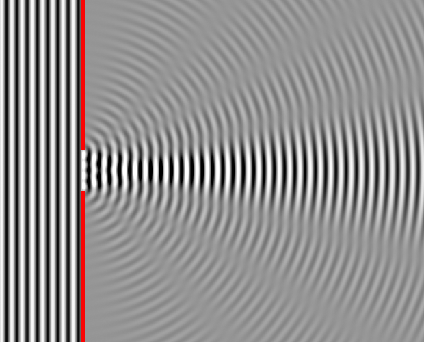
Caption: "Numerical simulation in matlab. Approximate diffraction pattern of a single 4-wavelength-wide slit".
This is a 2-dimensional diffraction pattern.
Waves come from the left and are diffracted through the slit.
Each point in the slit acts sort of like a point source of waves and the combination waves from each source gives rise to interference minima and maxima pattern which is the diffraction pattern.
You would see something like this in a water ripple tank experiment.
Credit/Permission: Dick Lyon (AKA User:Dicklyon), 2007 / Public domain.
Image link: Wikipedia: File:Wave Diffraction 4Lambda Slit.png.
In the case of sound waves, we only hear the sound waves and diffraction, and NOT see them.
Diffraction of sound waves happens all the time and we certainly notice the bending of sound around obstacles and its spreading out from apertures (e.g., doors and windows) which is diffraction in action.
But perceiving a clean sound diffraction pattern is rare though because it is usually washed away (i.e., averaged away) by multiple reflections of sound in the surroundings AND because diffraction is wavelength-dependent. A situation with multiple or a continuum of wavelengths of sound results in overlapping diffraction patterns that tend to wash each other out.
- Diffraction and Electromagnetic Radiation (EMR):
Diffraction is one of the main wave nature manifestions of EMR.
-
Question: Strong sunlight shining though window into
an otherwise unlit room:
- spreads out to illuminate the whole room equally.
- is just a beam that causes a bright square on the floor.
The statements are extreme limits. But which statement is most true?
Answer 2 is right.Note, you can often see the beam because dust particles reflect light to you, but light NOT headed toward your eyes is NOT seen.
Also the light scattered by the dust and the floor give some general illumination to the room. This light then scatters off the walls etc. and so you see the walls etc.
A laser pointer demonstrates this: you see the reflection of laser light from where the beam hits, but NOT the beam itself.
In the old days, I'd have a student who was a smoker breathe smoke into the laser light beam to demonstrate the reflection by smoke particles---but we can't do that any more.
I could also use chalk dust---but we don't have blackboards anymore.
You can also see a laser beam reflected off water drops as illustrated in the figure below (local link / general link: laser_aerosol.html).
Why NOT? The explication is in the figure below (local link / general link: diffraction_ratio.html).
One usually just notices a chopped piece of the wavefront---which looks like a beam to the human eye---and a shadow region.
Multiple sources and overlapping patterns of different wavelength tend to wash out any tiny, narrow-fringed diffraction pattern near shadow edges.
-
I've read somewhere if you look closely at the edges of
shadows in strong
sunlight, you
can make out a bit of a tiny
diffraction pattern.
But I've never managed to see this myself. Maybe a magnifying glass would help.
But for visible light, diffraction is NOT readily noticeable, and so we do NOT readily notice light as a wave phenomenon.
The spreading out of a beams from a window say is small and the diffraction pattern is usually washed out by multiple sources and reflections and the spread in wavelength of the beam.
In fact, we can usually just treat visible light as coming in light rays that travel in straight lines: i.e., exhibit rectilinear propagation.
But many useful optical effects and devices depend on diffraction. For example, diffraction from a diffraction grating is used to cause dispersion: see below in section The Dispersion of Electromagnetic Radiation.
- Diffraction, Wavefront Breaking, and Huygens Principle:
Well by color, but you do NOT know that color is a manifestation of wave nature by simple direct observations.
A direct manifestation is by following the oscillations of the electric fields and magnetic fields in electromagnetic radiation (EMR), but that is that is NOT easily done for high frequency EMR (e.g., visible light).
Throughout tens of thousands of years of human history, no one noticed the the wave nature of EMR until the 17th century and it wasn't widely accepted until the the 19th century (see Wikipedia: Light: Wave theory).
It turns out that the most obvious and easily accesible manifestation of wave nature is interference and diffraction. (Note, the use of the singular verb "is".)
And yes, EMR exhibits interference and diffraction.
-
Actually, when you think of it,
wave phenomena do NOT
necessarily
have to have
interference
and diffraction.
But, in fact, yours truly knows of
NO physical
waves that do NOT
have interference
and diffraction.
One can, of course, imagine wave phenomena without interference and diffraction. They would just be wave phenomena because they oscillate like waves.
Interference is usually thought of as happening with a only a few sources and diffraction with a large set or a continuum of sources.
In fact, the two terms interference and diffraction are synonyms and are used somewhat interchangeably. Convention often decides which term to use.
For example, the term interference is used in the terms constructive and destructive interference fringes (i.e., bands of high and low intensity) that occur with both interference and diffraction.
For another example, the pattern of interference fringes is usually called a diffraction pattern for either of interference and diffraction cases.
In the subsections below, we explicate interference and diffraction.

-
Electromagnetic radiation (EMR)
forms a continuum with
NO gaps from
zero
to infinite
wavelength---or
infinite to
zero
frequency.
- The Electromagnetic Spectrum Is a Continuum:
To explicate further, there are NO boundaries or gaps in EMR in the dimensions wavelength and frequency as far as we know.
This means that they form continuums---and so EMR forms a continuum---i.e., the electromagnetic spectrum is a continuum.
-
By continuum, we mean
an ordered set of entities that
loosely speaking has NO "missing points".
Rational numbers---which are numbers expressible as ratios of integers---have "missing points": for example sqrt(2) = 1.41421 ... ≅ 1.4 is within the boundaries of rational numbers, but is NOT a rational number: i.e., it CANNOT be expressed as ratio of integers.
Real numbers (which include rational numbers and irrational numbers) have NO "missing points", and thus form a continuum---in fact set of real numbers is the prime example of a continuum.
A more math-jargony way of distinguishing real numbers and rational numbers is to say that real numbers form a complete metric space and rational numbers do NOT.
-
Negative
frequency does NOT
usually arise for EMR
in any ordinary formalism.
However, for non-vacuum
systems,
you can exceed the medium light speed and overtake
EMR waves in principle,
and so encounter them in revese order in a sense,
and so maybe negative
frequency is sometimes used in such cases,
but yours truly does NOT know.
On the other hand, there are many systems where you can overtake mechanical waves, and so negative frequency is sometimes used for these cases.
- The Limits of the Electromagnetic Spectrum:
Above, we said there are no limits between zero and infinity in wavelength or frequency.
This is what classical electromagnetism predicts.
But there some qualifications:
- One qualification is just the limit on our on ability to detect
low and high EMR
frequencies.
Wikipedia gives
3 Hz as the conventional low limit
of extremely low frequency radio
and 300 EHz (300*10**18 Hz)
as the conventional high limit
on gamma rays.
But there may be more extreme limits unknown to
Wikipedia so far.
- Beyond classical electromagnetism,
quantum field theory suggests there
may be a true lower limit on
wavelength of
∼
Planck length l_p = sqrt(ħ*G/c**3) = 1.616199(97)*10**(-35) m
(with a corresponding true high
frequency limit).
The reason for this lower limit is simply that
theoretical physics
has NO established theory
for what happens at smaller scales.
- A true upper limit on
wavelength
(with corresponding true
frequency limit)
may be the size of the
universe---which we do NOT know
and may be infinite.
- The Electromagnetic Spectrum Illustrated:
The electromagnetic spectrum and the conventional wavelength bands are illustrated in the figure below (local link / general link: electromagnetic_spectrum.html).
- The Visible Band:
Human eyes sensitive to EMR wavelength in the visible band (fiducial range 0.4--0.7 μm) which band is illustrated the figure below (local link / general link: visible_band.html).
- Psychophysical Sensitivity to Visible Light:
Our psychophysical sensitivity to visible light is wavelength-dependent: i.e., color-dependent.
This is illustrated in the two figures below (local link / general link: human_luminosity_function.html; local link / general link: human_luminosity_function_prct.html).
- Polychromatic Light and White Light:
Often we just see light of mixed wavelength (i.e., polychromatic light) and then we have a psychophysical-sensitivity-weighted average response.
For example, the mixtures of colors in sunlight filtered through the Earth's atmosphere gives what we call white light because it looks white or white-yellow.
- Seeing Beyond the Visible Light Band:
Not all life sees just in the human visible light band.
Birds see a bit into the UV (Bird vision: Ultraviolet). But what color do they see?
Some snakes (rattlesnakes and other pit vipers and boa constrictors and pythons) have loreal pits on the sides of their heads in addition to eyes.
These loreal pits are sensitive to infrared light out to perhaps 8--12 microns. This allows these snakes to see the light emitted from hot bodies and thus they can see in the dark. See the Eye Design Book and the figure below.

Caption: An infrared thermogram (thermography image) of a mouse being eaten by a snake.
The image is false color, of course.
Darker is colder: i.e., longer wavelength.
Snakes are cold-blooded.
Who could feed a fellow mammal to a snake?
Credit/Permission: © User:Arno/User:Coen, 2006 / Creative Commons CC BY-SA 3.0.
Image link: Wikipedia: File:Wiki snake eats mouse.jpg.
Actually, humans can see a bit beyond the fiducial range 0.4--0.7 μm of the visible light band. See the figure below (local link / general link: human_luminosity_function.html).
- Why We see Visible Light (fiducial range 0.4--0.7 μm):
-
Question: Why out of all the electromagnetic spectrum
did human and most other
animal eyes evolve to be sensitive to the 0.4--0.7 micron band (i.e.,
visible light)?
The EMR in this band:
- has long enough wavelengths so that they don't damage organic molecules too much.
- is abundant since the Sun radiates most
strongly in this band.
- is abundant since the Earth's atmosphere
is very transparent in this band.
- has short enough wavelengths so that there isn't
much diffraction in light passing through the eye openings.
Diffraction would lead to inherent blurriness.
- All of the above.
Actually, it is very hard to say for sure, but 1, 2, and 3 all probably contributed.Probably NOT answer 4. One can see pretty sharply in the infrared. Diffraction isn't so bad at the shorter infrared wavelengths.
The fact that the Sun radiates most strongly in the visible band (fiducial range 0.4--0.7 μm) and the Earth's atmosphere is very transparent in this band seems coincidental. However, the concidence (which created abundant visible light) may be why vision became such an important sense for terrestrial biota.
- The Limits of the Electromagnetic Spectrum:
Subject to some qualifications on the limits which we discuss below in subsection The Limits of the Electromagnetic Spectrum.
The continuum of EMR is called the electromagnetic spectrum.

-
In order to analyze EMR
in spectroscopy, we
need to break it up into its constituent
wavelengths by the
process of dispersion
in order to create spectra.
- Polychromatic Electromagnetic Radiation:
Now almost any natural or artificial source of EMR gives EMR with a mixture of wavelengths: it is polychromatic EMR as opposed to monochromatic EMR which has single wavelength.
Exact monochromatic EMR is ideal limit that does NOT actually occur.
But the wavelength mixture in polychromatic EMR can be reduced in principle to as small as you like, but there are practical limits????.
An example of near-monochromatic EMR is a emission from a laser. For example, see the nearly monochromatic light green laser beam in the figure below (local link / general link: laser_aerosol.html).
- Dispersion:
We'd often like to analyze polychromatic EMR and see what the intensity or flux of the EMR is per wavelength.
-
Intensity or flux is energy per unit time per unit area which in
MKS is measured in watts/meter**2.
-
A primitive way is by selective reflection.
An object has particular color because it reflects that color absorbs other colors.
But the reflection process is rather complex and the reflected color is often still a mixture of wavelengths that can come from multiple non-contiguous bands.
Thus, reflection is just NOT a simple analysis tool to use and thus is NOT a good analysis tool to use.
A simple disperser is a prism which uses refraction to disperse the light.
Prisms and refraction are explicated in the figure below (local link / general link: refraction_prism.html).
- The Rainbow:
A much older disperser of light than human-made prisms and diffraction gratings (see below subsection How Does a Diffraction Grating Work?) is a cloud of water drops roughly opposite the Sun on the sky. The cloud gives us the rainbow.
The figure below (local link / general link: rainbow_explication.html) explicates the formation of the rainbow.
- The Solar Spectrum:
The rainbow is, of course, the spectrum of the Sun. But the water drops don't spread out (i.e., disperse) the wavelengths very much and give a rather imperfect spectrum.
Astronomers can do better in dispersing sunlight using diffraction gratings as illustrated in the figure below (local link / general link: solar_spectrum_image.html).
We'll discuss the solar spectrum and absorption lines in IAL 7: Spectra.
- Spectroscopy:
The analysis of dispersed EMR is called spectroscopy.
Spectroscopy is the most useful and important of all chemical analysis tools. In IAL 7: Spectra, we'll go into spectra and spectroscopy more deeply.
The prime instrument of spectroscopy is the spectroscope. A spectroscope is illustrated in the figure below (local link / general link: spectroscope.html).
- How Does a Diffraction Grating Work?
How does a diffraction grating work? A partial explication is given in the figure below (local link / general link: diffraction_grating.html).
- Dispersion:
We go into details about spectroscopy in IAL 7: Spectra and preview it a bit below in subsection Spectroscopy.
But to give the short answer as to why it is important, spectroscopy is the most important of all chemical analysis techniques and how we know what the cosmic composition is even though most of the observable universe is untouchable.
-
Group Activity:
Form groups of 2 or 3---NOT more---and tackle Homework 6 problems 7--12 on electromagnetic radiation (EMR).
Discuss each problem and come to a group answer.
Let's work for 5 or so minutes.
The winners get chocolates.
See Solutions 6.
-
In this section, we further explicate photons
beyond what was explicated in above subsection Photons.
- Four Treatments of Electromagnetic Radiation (EMR):
There are actually four treatments of electromagnetic radiation (EMR) all of which are useful in certain limits:
- In many applications, especially for
visible light,
you NEVER need to think of
EMR
as either a wave
or a photon.
You can just treat
EMR
as a continuous beam of stuff.
This treatment is called
geometrical optics
and the beams can be analyzed using conventional
light rays.
Geometrical optics
(including reflection and
refraction)
is all that is needed usually for simple
optical devices:
e.g., mirrors,
lenses,
eyeglasses,
binoculars,
telescope,
microscopes,
cameras,
etc.
For these devices, refraction
is treated using
Snell's law
(AKA the law of refraction),
but
interference
and diffraction
(which are NOT accounted for
in geometrical optics)
are deemed negiligible.
Geometrical optics is actually an emergent emergent theory from classical electromagnetism.
- On the other hand, when
EMR is propagating through
structures of size scale comparable or smaller than the
wavelength of the
EMR,
then treating
EMR as
a wave phenomenon
is essential because
diffraction
and interference
will be significant.
This treatment is directly classical electromagnetism which is an emergent emergent theory from quantum electrodynamics.
- On the third hand, when the interaction of
EMR with
individual
atoms
and
molecules
is important, it is correct and usually best to
consider EMR
as consisting of photons---it is
overwhelming simplest to do so athough in most cases NOT absolutely essential.
This treatment constitutes an emergent emergent theory from quantum electrodynamics.
-
Actually, people have found ingenious ways of dispensing with
photons even in
quantum mechanics---they
are devil's advocates.
Just to give a bit of science history, the concept of photons has been around since 1900 (originally being called the quantum of light).
But proof that photons are indispensable entities in physics was finally obtained only in the 1970s (e.g., Greenstein & Zajonc, 2005, p. 32--34).
But physicists had believed in them long before that---maybe since the 1920s---photons are just part of the paradigm of quantum mechanics.
In below section Photon Propagation in Gases, we consider a case where it is very useful to treat EMR as photons since the EMR is constantly interacting with free individual atoms, molecules, and/or electrons.
- At the most fundamental level is the
treatment by
quantum electrodynamics:
our most fundamental theory
electromagnetism.
Quantum electrodynamics
is used for the most elementary aspects of
electromagnetism
and the above three treatments of
EMR
are emergent theories
(i.e., exactly correct limiting cases that can be approached arbitrarily closely
in principle as far as we know and very usefully closely approached in practice) of fundamental
electromagnetism.
Quantum electrodynamics
itself emerges from the
standard model of particle physics
which in turn is believed to emerge from
theory of everything (TOE)
which we do NOT yet know.
- The Energy of a Photon:
What is the energy of an individual photon (i.e., the photon energy)?
For wavelength λ, it is given by the de Broglie relation:
E = hc/λ = 1.986445824*10**(-19) J-μm / λ_{μm} = 1.239841974 eV-μm / λ_{μm} ,where h is the Planck constant, c is the vacuum light speed, λ_{μm} is wavelength is measured in microns (μ), the Joule (J) is the MKS unit of energy, and the electron-volt (eV) is the microscopic unit of energy.
To understand the size scales a bit, we note that the energy to lift a kilogram 1 meter is about 10 J, a Watt-second = 1 J and 1 kW-hour = 3,600,000 J, and a photon from the visible band (fiducial range 0.4--0.7 μm) has photon energy of ∼ 2 eV.
The de Broglie relation is an inverse relation: λ ↑ E ↓ and λ ↓ E ↑ .
Even for gamma rays with wavelengths typically less than 10**(-5) μm (see the figure below: local link / general link: electromagnetic_spectrum.html and Wikipedia: Gamma ray: General characteristics), the energy of a single photon is microscopic: i.e., typically of order and greater than 10**(-14) J.
- Photon Mysteries:
Now I know what you are thinking.
How big is a photon and what is its shape?
Well, we don't really know.
It may be a point particle---or maybe NOT.
But we think of it as being a point particle in a continuum superposition of positions.
The distribution of those positions is, in fact, a wave phenomenon and gives the wave nature of EMR.
-
The description of the wave nature
of photons
is, recall, via
the wave function (common symbol Ψ)
of
quantum mechanics.
The spread/collapse process is called wave function collapse.
How fast is wave function collapse?
We don't really know. It may exceed the vacuum light speed as one of the quantum mechanical superluminal effects we discussed above in subsection Qualifications About the Vacuum Light Speed as the Fastest Physical Speed.
Yours truly is NOT sure if we know better than that---but maybe yours truly is just out of touch.
Why we do NOT notice the particulate nature of EMR in most situations including all of everyday life?
Any macroscopic amount of EMR contains so many photons that the particulate nature is washed out.
Similarly one does NOT notice that water is made of molecules of H_2O.
-
Recall the discussion in section
Electromagnetic Radiation: Creation and Destruction
that single photons CANNOT be seen---but one
can see very small numbers under dark conditions.
Even if you have just one photon, there is a wave-like and spread out nature to the photon because of the wave-particle duality quantum mechanics that we discussed in above in the Introduction.
We explicate the wave-particle duality of single photons with the interference experiment illustrated in the figure below (local link / general link: qm_double_slit.html).
- Danger:
EMR from the ultraviolet and blueward in wavelength is dangerous to life.
The further blueward, the more dangerous. So gamma rays are the most dangerous EMR. However in sunlight, ultraviolet is the most most dangerous EMR to penetrate the Earth's atmosphere.
Dangerous EMR can damage organic molecules such as DNA (see figure below (local link / general link: dna_rotating.html).
But that does NOT mean that NUMBER OF and ENERGY OF photons are exactly compensatory quantities: many reactions with matter are sensitive to the energy of the individual photons.
Photons from the ultraviolet and blueward region of the electromagnetic spectrum are ionizing radiation.
They are individually energetic enough that they can knock electrons off atoms and molecules in a process called ionization.
Every ionization is done by one high-energy photon. Lower energy photons, no matter how, numerous will NOT ionize atoms and molecules---at least NOT in a direct sense. So they are relatively safe.
If the ejected electron is sufficiently fast, it can ionize further atoms and molecules creating a cascade of fast electrons and ionizations. The resulting ions (i.e., the charged atoms and molecules) can be chemically destructive to organic material.
-
The whole story of ionizing radiation
is a lot more complex than the story just given.
Other damaging processes besides straightforward ionization also turn up.????
As well as ionizing photons, particles from radioactive decay are also ionizing radiation.
The damage from ionizing radiation can cause long-term health effects: most importantly various kinds of cancer.
Intense ionizing radiation will cause radiation sickness which is actually many things (but some more than others) since ionizing radiation if sufficiently penetrating can cause damage anywhere in the human body and in any other kinds of biota bodies too.
- In many applications, especially for
visible light,
you NEVER need to think of
EMR
as either a wave
or a photon.
You can just treat
EMR
as a continuous beam of stuff.
This treatment is called
geometrical optics
and the beams can be analyzed using conventional
light rays.
Geometrical optics
(including reflection and
refraction)
is all that is needed usually for simple
optical devices:
e.g., mirrors,
lenses,
eyeglasses,
binoculars,
telescope,
microscopes,
cameras,
etc.
For these devices, refraction
is treated using
Snell's law
(AKA the law of refraction),
but
interference
and diffraction
(which are NOT accounted for
in geometrical optics)
are deemed negiligible.
-
Photons are useful---and correct---for thinking about how
EMR propagates through a
gas containing any or all of
atoms,
molecules,
ions,
and
electrons.
This is because there is lots of photon and gas interaction and interference and diffraction have negligible effect.
-
The particle-like, wave-like, and
light-ray propagation modes
are consistent when propagation
is considered from a general understanding of the photon behavior
as mentioned above.
The radiative transfer process is explicated in the figure below local link / general link: photon_escape.html).
A close-up illustration of a
photon or
photon packet
doing a
random walk
is given in the figure below
(local link /
general link: photon_escape_random_walk.html).
The figure below
illustrates a
random walk process, but
NOT for
photon packets.

Caption: "This is a simulation of the Brownian motion of 5 particles (yellow) that collides with a large set of 800 particles leaving 5 blue trails of random walk motion with one yellow particle with a red velocity vector represented."
This animation is NOT a photon case, but it gives you the right idea of how a photon does a random walk scattering its way through a gas of atoms and/or molecules.
Credit/Permission: ©
User:Lookang,
2012 /
Creative Commons
CC BY-SA 3.0.
Image link: Wikipedia:
File:Brownianmotion5particles150frame.gif.
The figure below (local link / general link: random_walk_3d.html) illustrates three generic random walks and gives some mathematical insight into the random walk process.
The figure completes our discussion of photon radiative transfer by random walks.
Form groups of 2 or 3---NOT more---and tackle
Homework 6
problems 12--16 on electromagnetic radiation (EMR)
and photons.
Discuss each problem and come to a group answer.
Let's work for 5 or so minutes.
The winners get chocolates.
See Solutions 6.
Group Activity: