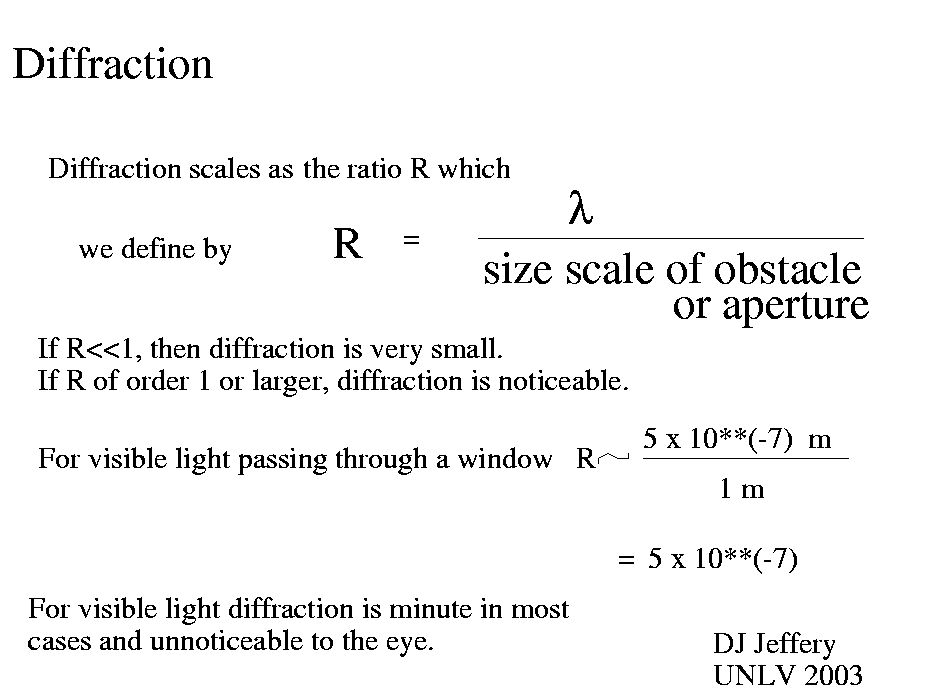
Figure: How the diffraction ratio describes the transition from physical optics to geometrical optics
Image 1 Caption: Image 1 Image 1 gives the definition diffraction ratio R for electromagnetic radiation (EMR) To recapitulate from the image, the diffraction ratio is the ratio light wavelength λ to characteristic size of an obstacle b breaking a wavefront of plane waves.
Note, diffraction ratio is just a nonce term defined by yours truly.
Further explication:
- Physical optics
treats light as a wave phenomenon obeying
classical electromagnetism
which is the macroscopic limit of
quantum electrodynamics
which is the most fundamental theory of
electromagnetism
we have.
- Geometrical optics
is an emergent theory from
classical electromagnetism
in the limit that wavelength over characteristic size of
an obstacle is zero.
In geometrical optics, light is treated just as light rays that have rectilinear propagation except for reflection and refraction.
A collection of light rays in one propagation direction can be called a light beam.
- Hereafter, we will mostly discuss apertures (a special case of an obstacle)
rather than general obstacles, because that
is how people usually think about diffraction cases and how they usually study them
in introductory courses.
However, the aperture case generalizes to general obstacles.
For example, a finite obstacle breaking a wavefront is almost the
same situation as for an aperture of the same shape as the projected
shape of the obstacle with light and dark fringes being interchanged as per
Babinet's principle
which we will not discuss.
- In geometrical optics,
the ideal beam transmitted through an aperture perpendicular to the incident
beam direction just has the aperture shape in
cross section
and extends away from the aperture in the third dimension.
- It can be plausibly shown by a somewhat intricate argument
(partially given by, e.g., HZ-338--339)
that the transmitted beam broadens in the far field limit (i.e., much farther
in the third dimension than the aperture characteristic size) from the
incident beam direction to
1st order
in small angle by the angle (which we are calling the diffraction ratio)
R = (λ/b) radians = approximately (λ/b) times 60 degrees
where the angle is subtended from the beam center (however that is best defined for a given case) and the first formula gives the angle in radians and the second in degrees. The edge of the transmitted broadened beam is, in fact, the first completely destructive interference band. Beyond the first completely destructive band extends the pattern of constructive and destrucive interference bands: i.e., the diffraction pattern. In the jargon of the diffraction, the constructive bands are called bright fringes and the desctructive bands are called dark fringes.Clearly, if λ/b << 1, the broadening of the edge of the transmitted broadened beam from rectilinear propagation is very tiny and often unnoticeable to casual observation.
It is also true if λ/b << 1, the bright fringes are very faint and often unnoticeable to casual observation, except the transmitted broadened beam which is very bright and is the bright central fringe in the jargon of diffraction patterns.
- In the case of the example in the image, where
λ = 500 nm = 5*10**(-7) m (which is green light)
and an aperture that is 1 m in size scale (e.g., a typical window size), we find
R = (λ/b) radians = 5*10**(-7) radians = approximately 3*10**(-4) degrees
which is unnoticeable to casual observation from rectilinear propagation.However, if aperture size scale were 10 micrometers, then the broadening would be a somewhat noticeable: i.e.,
R = (λ/b) radians = 5*10**(-2) radians = approximately 3 degrees .
In this case, many dark and bright fringes would be noticeable: i.e., a noticeable diffraction pattern would be seen. This case is similar to the case illustrated and explication in Optics file: diffraction_pattern_square.html.
- Image 2 Caption: A schematic diagram for a single slit diffraction pattern (resulting from a single slit aperture breaking a wavefront) showing both the intensity plot and diffraction pattern image. The slit length (which is in the direction perpendicular to the image plane) is much larger than the slit width. The first complete destructive interference (i.e., the first dark fringe minimum) is shown. The diffracton pattern is for much closer than the far field limit, and so does not exactly correspond to explication above. Nevertheless, the first dark fringe miminum is the edge of the central bright fringe and in the limit of wavelength over slit width going to zero becomes the edge of the transmitted light beam made of light rays in rectilinear propagation.
- The general conclusion of the above explication is that for visible light beams broken by obstacles of human size scale, diffraction is ordinarily unnoticeable to casual observation.
Additionally, usually there are multiple source of visible light that tend to wash out diffraction patterns.
Additionally moreover, the visible light forming the diffraction pattern is usually polychromatic light---it consists of a largish continuous range of wavelengths. Each wavelength has its own diffraction pattern. The result is a continuum of overlapping diffraction patterns. To the eye, the result may be something of a washout or a very complex pretty diffraction pattern. One can largely eliminate, the overlapping diffraction patterns by using a laser beam which is nearly monochromatic light.
So ordinarily we don't notice the diffraction of visible light for several reasons.
- Ways of seeing diffraction patterns without elaborate equipment:
- If you have a bright source of light shining through a small hole
the shadows cast will have a bright fringe bordering them which is the visible
part of a diffraction pattern
(e.g., HZ-329).
For an object like a pencil, you might see the see a faint long bright fringe in
the center of the shadow.
The bright center fringe is explained by
Babinet's principle.
- A way of seeing a rather complex diffraction pattern is to put a water drop
on a glass plate and hold it close to the eye and look at a bright point source
through the water drop
(e.g., HZ-329).
The diffraction pattern will be complex pattern bright and dark fringes.
- An intense monochromatic laser in an otherwise dark environment will give
observable diffraction patterns around the shadow of objects.
See
Hyperphysics:
Diffraction by Opaque Edges.
- Image 2 Caption: A schematic diagram for a single slit diffraction pattern (resulting from a single slit aperture breaking a wavefront) showing both the intensity plot and diffraction pattern image. The slit length (which is in the direction perpendicular to the image plane) is much larger than the slit width. The first complete destructive interference (i.e., the first dark fringe minimum) is shown. The diffracton pattern is for much closer than the far field limit, and so does not exactly correspond to explication above. Nevertheless, the first dark fringe miminum is the edge of the central bright fringe and in the limit of wavelength over slit width going to zero becomes the edge of the transmitted light beam made of light rays in rectilinear propagation.

- Credit/Permission: ©
David Jeffery,
2003 / Own work.
Image link: Itself.
- Credit/Permission: ©
User:Jkrieger,
2012
(uploaded to
Wikimedia Commons
by User:老陳,
2012) /
CC BY-SA 3.0.
Image link: Wikimedia Commons: File:Single Slit Diffraction First Minimum.svg.
File: Optics file: diffraction_ratio.html.