General Caption: Images illustrating electromagnetic waves.
Features:
- Image 1 Caption:
An animation
showing ray of
electromagnetic radiation (EMR)
propagating
to the right obliquely.
The ray could be part of a continuum of rays making a beam of finite geometrical cross section such as a plane wave. See Image 3 below for an illustration of a plane wave.
In fact, for definiteness, let's speak of the beam in the animation as a plane wave.
- The small Greek letter
lambda λ is the common
symbol
for wavelength.
- A wavelength is the length of a complete
spatial cycle of the wave motion.
- The oscillations of the
electric field (E-field)
(shown in red)
and the
magnetic field (B-field)
(shown in blue)
have a directions in real space, but they extend in abstract
electric field space
and magnetic field space.

- Image 2 Caption: An analogue animation to Image 1, but now moving directly to the right.
- The lengths of the vectors are really the magnitudes or strengths of the electric field and magnetic field.
- The electric field and magnetic field are perpendicular to each other and the propagation direction.
The oscillations being perpendicular to the propagation direction makes EMR a transverse wave phenomenon like waves on a string.
- In EMR, the electric fields and magnetic fields are coupled: i.e., are mutually interacting.
In fact, a time-varying electric field creates a time-varying magnetic field and vice versa---they create each other to paraphrase Jack Nicholson (1937--).
And they must do so for EMR to be self-propagating.

- Image 3 Caption: A diagram of a square segment of linearly polarized electromagnetic radiation (EMR) plane wave.
- Ideal plane waves, extend to infinity. Realistic ones have a finite extent with complicated edges in general. However, a small enough portion of any wavefront (e.g., of spherical waves as in Image 4 below) approximates a plane wave.
- The directions of the electric field (E-field) (shown as red arrows) and the magnetic field (H-field) (shown as green arrows) are shown in in real space, but their extent is in, respectively, abstract electric field space and abstract magnetic field space.
Note for magnetic fields either the symbol E or symbol H may be used. The two symbols do NOT mean quite the same thing, but our purposes they do.
- In the plane wave, the electric field and the magnetic field have a constant direction and magnitude throughout the any plane of the plane wave. These planes are perpendicular to the propagation direction given by black arrow S.
- The electric field and the magnetic field are perpendicular to each other and are perpendicular to the propagation direction.
- The plane wave is a monochromatic sine wave. The sine wave behavior (which represents extent in abstract electric field space and abstract magnetic field space) is shown by the red and green bands.
- As for Images 1 and 2, the small Greek letter lambda λ is the symbol for wavelength.
- The sources of the EMR beams in the images above may be oscillating electric charges at the right, but NOT shown in the images.
- Linear polarization:
- The beams in the images above are
linearly polarized.
This means that the electric field and magnetic field are confined to two perpendicular planes.
- Real finite beams are made up of many
photons (the particles of
EMR) with all orientations of
the electric field
and magnetic field
perpendicular to the
propagation direction being possible.
- The vectors of the photons do NOT
cancel microscopically---or else
there would be a lot less EMR
than there is.
- Sources that radiate EMR
from their own internal heat energy
naturally radiate
unpolarized light
in which all orientations of
the electric field
and magnetic field perpendicular to the
propagation direction occur with equal weighting.
- EMR
can be linearly polarized
through various processes like
reflection
and transmission through polarizing materials like those
that are used in polarized sunglasses.
A filter that linearly polarizes
is called a polarizer.
- There is also
circular polarization---but that is
the story for another place.

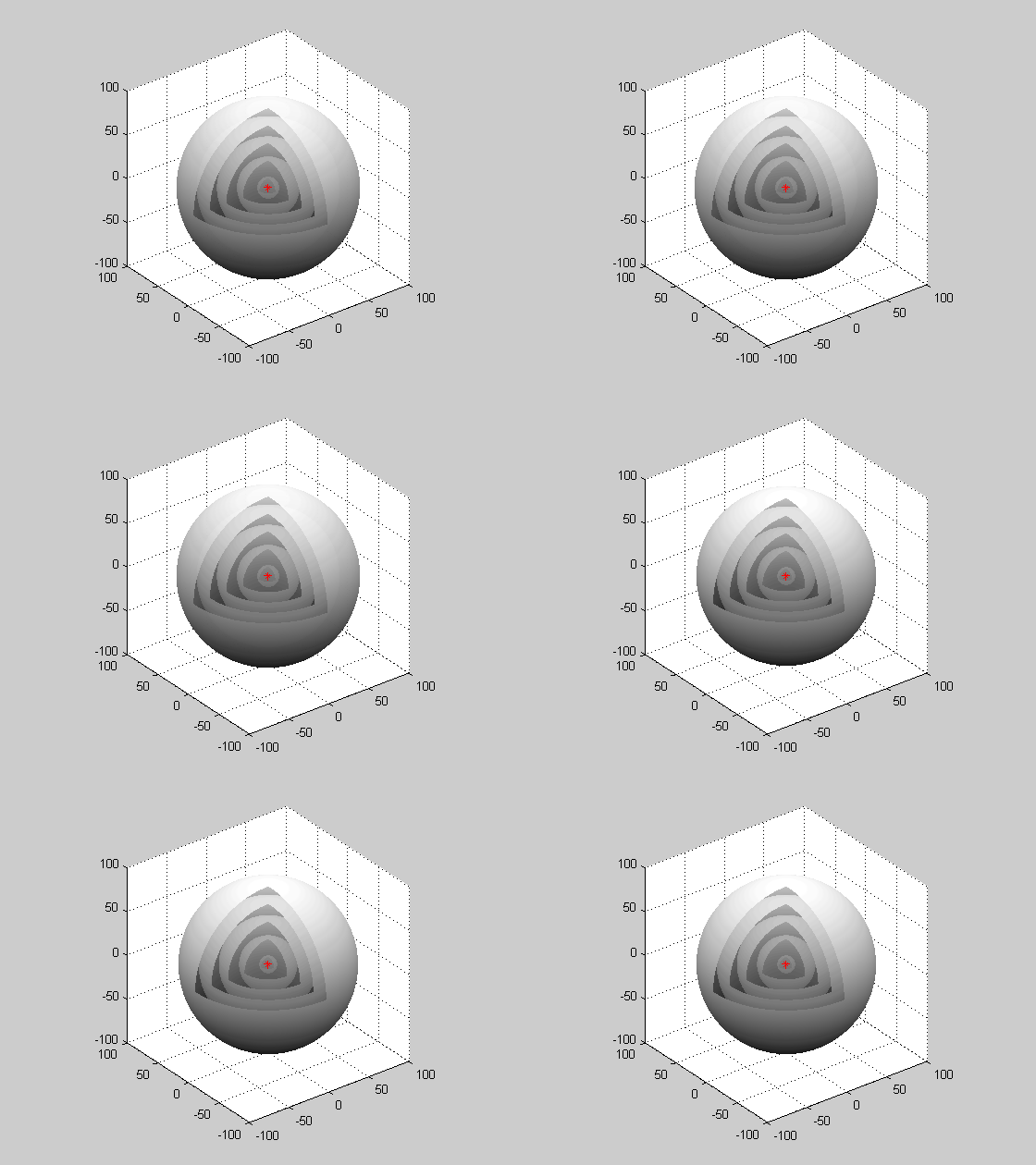
- Image 4 Caption: A cutaway animation of a generic spherical wave from a point source.
Far from the point source, a small part of a wavefront will approximate a plane wave.
- Image 2 Caption: An analogue animation to Image 1, but now moving directly to the right.
-
Images:
- Credit/Permission: ©
Loo Kang Wee
(AKA User:Lookang),
2011 /
CC BY-SA 3.0.
Image link: Wikimedia Commons: File:Electromagneticwave3Dfromside.gif.
- Credit/Permission: ©
Loo Kang Wee
(AKA User:Lookang),
2011 /
CC BY-SA 3.0.
Image link: Wikimedia Commons: File:Electromagneticwave3D.gif.
- Credit/Permission:
©
User:Chetvorno
2020 /
CC BY-SA 1.0.
Image link: Wikimedia Commons: File:Plane electromagnetic wave.svg.
- Credit/Permission:
© Jonathan Papa
(AKA Jonpapa),
2011 /
CC BY-SA 3.0.
Image link: Wikimedia Commons: File:Spherical Wave.gif.
File: Electromagnetic Radiation file: emr_animation.html.