The Carnot Engine
Carnot engine
or
Carnot cycle
was discovered by
Sadi Carnot at least in some form if not quite what we know today.
The actual history is beyond my scope.
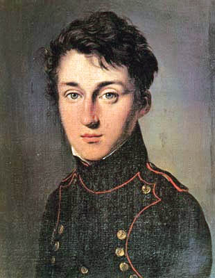
Nicolas Leonard Sadi Carnot (1796--1832): a pioneer of
thermodynamics.
Sadi Carnot in the dress uniform of a student of the Ecole Polytechnique.
Carnot is noted for his discovery of the
Carnot engine or
Carnot cycle.
The Carnot engine has the most
efficient cycle possible for a heat engine or refrigerator.
Credit: Unknown artist to the web.
Wikipedia judges its copyright status as uncertain.
But it must have been painted no later than the 1820s and
surely the artist's copyright is now long expired if it ever
exited.
Download site
Wikipedia: Image:Sadi Carnot.jpeg
He also had a famous father,

Caption: "Lazare Carnot" with braids and
epaulets.
Lazare Carnot (1753--1823), one of the French Revolution leaders.
Carnot was called the ``Organizer of Victory''.
Credit: Unknown artist. Uploaded by User: Nk in 2005.
Linked source: Wikipedia
image
http://en.wikipedia.org/wiki/Image:Lazare_carnot.jpg.
Public domain.
What
Carnot imagined (at least the ideal Carnot if not the
Carnot of history) was a reversible THERMODYNAMIC ENGINE.

Caption: "Sadi Carnot's pison-and-cylinder diagram from 1824".
A and B may
Carnot's
HOT BATH and COLD.
Credit: Sadi Carnot
(1796--1832). Uploaded by User:
Sadi Carnot who is not
Sadi Carnot.
Linked source: Wikipedia
image
http://en.wikipedia.org/wiki/Image:Carnot-engine-1824.png.
Public domain at least in USA.
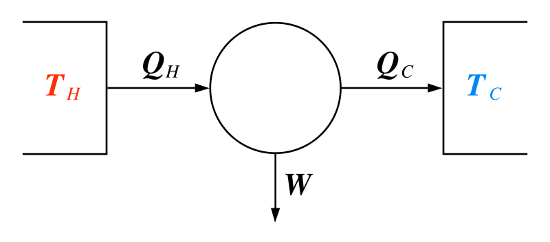
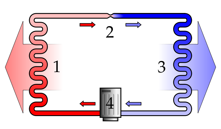
This machine now is called the
Carnot engine.
Run forward, it is a
heat engine.
Run in reverse, it is a
refrigerator.
The Q_H, Q_C, and W quantities are the same if the
Carnot engine
is run forward
as heat engine
or in reverse
as
refrigerator.
Thus, one has
F_eff = G_eff = W/Q_H = 1- Q_C/Q_H
for the
Carnot engine.
        Q_H_hyp > Q_H

        and

        recall

        W = Q_H - Q_C    where W is output

                 and

                 where Q_H is absorbed from the HOT BATH and Q_C is rejected to the COLD BATH

        and

        W_hyp = W = Q_H_hyp - Q_C_hyp  where W is work input

                 and

                 where Q_H_hyp is rejected to the HOT BATH and Q_C is absorbed from the COLD BATH.


        Subtracting the former from the latter, we find

        0 = ( Q_H_hyp - Q_H ) - ( Q_C_hyp - Q_C )

        or

        ( Q_H_hyp - Q_H ) = ( Q_C_hyp - Q_C ) > 0
The upshot in words is that no net work is done and
yet a finite amount of heat
( Q_H_hyp - Q_H ) > 0
has been moved from the COLD BATH to the HOT BATH.
From an overall perspective, there is a spontaneous flow of
heat from
HOT to COLD.
A similar argument shows that if you have a
heat engine
more efficient than a
Carnot engine,
then
you can turn
heat entirely
into work without rejecting any net
heat
to a COLD BATH.
Carnot
did not know of the
second
law of thermodynamics: it was formulated after his day.
But he did know that no one had every seen
a spontaneous flow of
heat from
HOT to COLD
nor a
heat engine
without rejection to a COLD BATH.
The ideal
Carnot
(if not the Carnot of history)
argued that
Carnot heat engine
must be the most efficient
heat engine
and
the most efficient
refrigerator
possible.
In the above, arguments our hypothetical
heat engine
and
refrigerator
that are more efficient than
the Carnot engine
DO violate the
second
law of thermodynamics and cannot exist.
Question: Now I know what you are thinking,
can a Carnot engine exist.
- No. It's a complete myth.
- Yes. They used everywhere. They are wonders.
You just don't hear much about them just like you
never hear much about
spontaneous human
combustion though it happens to tens of people every year
(according to David St. Hubbins).
- Almost. Not quite.
Answer 3 is right.
You can almost build a
Carnot engine.
The main trick is to only let heat flows occur when
the
working fluid
is in thermal contact with
the HOT BATH and the COLD BATH
and only let those flows occur
between vanishingly small temperature differences.

Caption: "Pressure-volume (p-V)
diagram for the Carnot cycle."
Credit: User Keta in 2006.
Linked source: Wikipedia
image
http://en.wikipedia.org/wiki/Image:Carnot_cycle_p-V_diagram.svg.
Use under
GNU
Free Documentation License
The PV diagram plots the
pressure
and
volume of the
working fluid
during a full cycle of the
the Carnot engine.
You could imagine the working fluid
as contained in a cylinder with a piston---just like in
Sadi Carnot's image
http://en.wikipedia.org/wiki/Image:Carnot-engine-1824.png
The piston pushes out when the
working fluid
does work and pushes in when work is done on the
working fluid.
The
Carnot engine
is running in a cycle and hence the curve forms a closed loop.
As the working fluid
expands (1--3), it does thermodynamic work (PdV;
as it contracts (3--1)
PdV work is done on it.
The less steep segments are
isotherms where
working fluid absorbs (when expanding)
or rejects (when contracting) heat
at ZERO
temperature gradient
(or difference).
This is the magic trick of the
Carnot engine
to make heat flow
at ZERO
temperature gradient.
If you could actually do this, then there would be no change in
entropy
and, thus the process would be REVERSABLE---you could make the
heat flow either way.
Well it can't actually be done quite.
But, in principle, one could approach
ZERO
temperature gradient
flow of heat
as closely as you like.
Just let temperature gradient
be very small and let the heat flow
very slowly.
Such ideal slow processes are called
quasistatic processes:
the system is always vanishingly
close to thermodynamic equilibrium
in a quasistatic process.
ZERO
temperature gradient
flow of heat
is the ideal limit of an actual physical process.
The steeper segments
PV diagram
are
adiabats
along which no heat flows occur
to or from the working fluid.
No entropy changes occur in
working fluid,
HOT BATH, and COLD BATH, along an
adiabat where
thermodynamic equilibrium
is maintained in all elements of the system.
To maintain exact
thermodynamic equilibrium
during changes the adiabats
are also quasistatic processes.
Since no entropy changes
occur during the quasistatic
adiabats, they
are REVERSIBLE and the
system can be run up or down them.
We conclude that all segments in the
PV diagram
are REVERSIBLE as an ideal limit.
So the whole cycle in the PV diagram
can be run either way since entropy of the
system doesn't change going either way.
Going 1, 2, 3, 4, 1, as shown in the
PV diagram,
yields net PdV work
since the expansion segments 1-2 and 2-3 have more area under them than the
contraction segments 3-4 and 4-1.
In this direction, the
Carnot engine is
a heat engine
moving thermal energy
from the
HOT BATH to the COLD BATH and doing
PdV work.
Going 1, 4, 3, 2, 1, as NOT shown in the
PV diagram
absorbs net PdV work
since the contraction segments 3-2 and 2-1 have more area under them than the
expansion segments 1-4 and 4-3.
In this direction, the
Carnot engine is
a refrigerator
moving thermal energy
from the
COLD BATH to the HOT BATH and absorbing
PdV work.
So the Carnot engine
is the reversible engine
Sadi Carnot
imagined.
Thus, the Carnot engine
is the most efficient
heat engine
and
refrigerator.
You can't quite build an ideal
Carnot engine.
But you can get very close.
Question: If a nearly ideal
Carnot heat engine
can be built, why
are they not widely used?
- They are dreadfully dangerous.
- They CANNOT built: the instructor has been lying.
- They are pretty powerless.
- All of the above.
Answer 3.
A nearly ideal
Carnot heat engine
must operate very slowly since all the segments must
be quasistatic.
In particular, the
heat transfers
must happen over
NEARLY ZERO
temperature gradients.
The lower the temperature gradients,
the slower
the heat transfer---we are just asserting this, but
it's true.
Carnot engines
do have special experimental uses.
But actually the only one I know of is to measure
temperature
in some special cases.
You can for example build a
Carnot engine
using a gas as a
working fluid.
They may be mostly small desktop affairs with tubes and cylinders and pistons---just
guessing.
The last point leads us to the ideal maximum efficiency and mimimum reverse
efficiency we have discussed above.
The
Carnot engine
as it is reversible has
F_eff = G_eff= 1 - Q_C/Q_H
and F_eff is the biggest that can be obtained for a
heat engine
and
G_eff is the lowest that can be obtained for a
refrigerator.
It can be shown---but we won't do it---that for the
Carnot engine
the ratio
Q_C/Q_H = T_C/T_H ,
where the
temperatures
are Kelvin temperatures.
This leads to our results
F_eff_max = 1 - T_C/T_H ,
and
G_eff_min = 1 - T_C/T_H .
These ideal results can never be quite obtained.
And, of course, people don't even try to get extremely close
usually since they don't want
the nearly ``powerless''
Carnot engine.
Nevertheless the ideal efficiency results set absolute limits on
what is obtainable and guide designers in
getting the best they can out
heat engines
and
refrigerators.
For actual
heat engines there
is often something to be gained by making T_C/T_H as small
as one can subject to other desiderata: i.e., safety and high power.
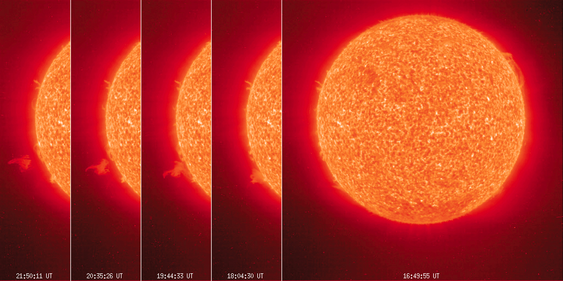 A UV series of images of the Sun with an eruptive prominence.


