

Caption: A schematic diagram of a Schmidt-Cassegrain telescope.
Credit/Permission: User:Griffenjbs, 2009 / Public domain.
Image linked to Wikipedia.
 Supplementary Lab Preparation:
The items are often alternatives to the required preparation.
Supplementary Lab Preparation:
The items are often alternatives to the required preparation.
Quiz Preparation:
Caption: A student
at the University of British Columbia (UBC)
in studying mode for
final exams.
Credit/Permission: User:Gnarlycraig,
2009 /
Public domain.
Image linked to Wikipedia.
The quiz might be omitted if it's not feasible or convenient.
The students may or may not be informed ahead of time of quiz omission
depending on the circumstances.
The quizzes in total are 40 % of the course grade.
However, only the top five quiz marks are counted.
In preparing for a quiz,
go over the Required Lab Preparation.
The Supplementary Lab Preparation
(see above) could help, but is only suggested if you
feel you need more than the required Required Lab Preparation.
There is no end to the studying you can do, but it is only a short quiz.
One to two hours prep should suffice.
There will be 10 or so questions and the time will be 10 or so minutes.
The questions will range from quite easy to challenging.
Some of the questions will be thinking questions. You will have to reason your way
to the answers.
There may or may not be a prep quiz to
test yourself with ahead of the lab period.
The solutions might be posted at Telescopes: Quiz Solutions. after the quiz is given. Whether they are or not depends on the circumstances of each individual semester.

Caption: Plato (428/427--348/347 BCE) and Socrates (circa 469--399 BCE) in a Medieval image.
Here the disciple seems to be instructing the master/mentor using the Socratic method.
The basic pose is much like in intro labs.
Credit/Permission: Medieval artist, Middle Ages (probably 1000--1400) (uploaded to Wikipedia by User:Tomisti, 2007) / Public domain.
Image linked to Wikipedia.
In case the weather is not good for observing, you need to have an alternate indoor lab ready. You will have to consult with the lab coordinator and/or other lab instructors. Alternative labs can be found at Catalog of Introductory Astronomy Labs. Usually, an inside lab from this semester's Lab Schedule would be appropriate. If there is no better option, yours truly suggests Lab 16: Hubble's law since it is quite short and easy to prep for.
Recall the following for Las Vegas, Nevada: (1) Location: 36 degrees 10'30" N 115 degrees 08'11" W, (2) Conversions to Universal Time (UT) PST=UTC-8, UTC=PST+8, PDT=UTC-7, UTC=PDT+7.
Usually, the Universal Time (UT) of observing will be one day plus the local calendar date at 4 or 5 am: Date and time: , .
They do the same things, but there is some rearrangement of functions and renaming.
You and the students have to get used to switching back and forth.
The pages Telescope Operation and List of Tricks for C8 Telescopes assume the old pads.
The standard eyepiece with the C8 telescope is 40-mm.
The students use that for some observations.
Each student group will also use one of the 18-mm, 12-mm, or 9-mm eyepieces.
Distribute these non-standarrd eyepieces so that there is at least one of each focal length and preferable two or more of each focal length in use.
The non-standard eyepieces are kept in boxes labeled by focal length.
At the end of the lab, make sure you get all the non-standard eyepieces back and back in their proper box. Students have a tendency for walk off with them in in their pockets.
The standard eyepieces should be back on the C8 telescopes.
Like many others, I have the students put standard eyepieces on the pillars when they come off the C8 telescopes so that they are obviously there to be put back on after the non-standard eyepieces are done with.
If the storeroom C8 is functioning, demonstrate telescope use with pad.
You will need one of the heavy black boxes to transform wall power to C8 power.
If the storeroom C8 is NOT functioning, you may optionally get out an old model telescope from the storeroom to demonstrate telescope use. You may have practice with it a bit.

Caption: "Red foxes (Vulpes vulpes) at the British Wildlife Centre, Horne, Surrey, England." (Slightly edited.)
Credit/Permission: © Keven Law, Photo 2008 Aug17 / Creative Commons CC BY-SA 2.0.
Image linked to Wikipedia.
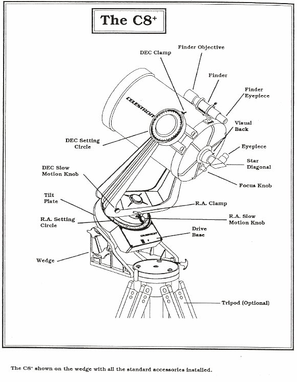
Our telescopes are Celestron C8's.
A C8 is a popular Schmidt-Cassegrain telescope.
Below is a schematic diagram of a Schmidt-Cassegrain telescope.
Caption: A schematic diagram of a Schmidt-Cassegrain telescope.
Some details of a Schmidt-Cassegrain telescope:
Highly exact spherical mirrors are vastly easier to construct than any other kind of curved mirror.
The diameter of the primary is the main parameter of any telescope. It is the first parameter anyone should know or ask about.
The reason for this is that the light-gathering power of a telescope is proportional to the square of the diameter.
The primary gathers the light from the observed object (e.g., an astronomical object).
The primary begins the process of image formation.
The purpose of the secondary is to allow the physical length of the telescope to be about half the optical path from primary to the formed real image (see below for real image).
The light reflects from the secondary and is directed through a hole in the primary where the real image forms.
If there were no secondary, the real image would form in well in front of the telescope where it would be very awkward to view.
But the diagram shows (with some close looking and imagination) how light rays from every part of a distant object make it to the real image, and so the image is complete.
But we can say a bit more.
When the image is in focus, the beam group coming from a point light source outside the telescope are focused to a point where it is observed (in some sense that needs more explication).
It doesn't matter what shape the beam group cross section had along the way since the beam group is focused to a point where it is observed.
But if the image is out of focus, the beam group is NOT focused to a point, but to some shape that is like the beam group cross section.
Since the telescope aperture is circular, the beam group cross section would be circular image for a point light source if the secondary were transparent to incoming beams.
Since the secondary is NOT transparent, you get a donut image for a point light source. The hole in the donut is the shadow of the secondary.
Yours truly thinks this is the gist, but there is a lot more detail to image formation. See also Collimating a Schmidt-Cassegrain Telescope.
It may seem odd that the real image can be complete given that there is a hole in the primary and that the secondary occults (i.e., blocks) part of the aperture.
But the diagram shows (with some close looking and imagination) how light rays from every part of a distant object make it to the real image, and so the image is complete.
A real image can be observed directly in the directions that the light rays are traveling as they diverge from the real image or it can be cast on a screen or recorded on photographic film or recorded digitally by a CCD camera.
The diagram shows a representative set of light rays that converge to form representative points on the real image.
The greater the magnification of the eyepiece, the smaller the field of view (FOV): there is a trade-off.
The FOV is circular because the telescope aperature is circular.
The telescope aperture and the eyepiece limit the FOV: i.e., limit how far off the optical axis (the symmetry axis of the telescope). one can see.
For example, a point light source too far off the optical axis of the telescope, can't shoot a light ray that will make it to the primary.
Objects sufficiently far away that the light rays from them are effectively parallel are said to be at optical infinity. in optics jargon
Optical infinity is often not the far. For small telescopes (like the Celestron C8 telescopes), it could be of order of magnitude 10 meters.
By focusing, objects at less than optical infinity can be focused, but how close they can be depends on your focusing setup.
For C8 telescopes, focusing for a distance less than the length/width an ordinary classroom is NOT possible.
Image linked to Wikipedia.
We name the 12 parts that the students are required to know while pointing to them on a demonstration C8 or on drawn diagram if we don't have a demonstration C8.
Tell the students to look at the unlabeled C8 in their lab manual.
We just rattle them off and describe a few of their functions.
For the C8 experience, saying how to slew with the pad and change the rate of slew is vital.
We will have to go over this again and again during the night.
Never slew by hand or rest weight on the C8's.
It is a lab question for the students to identify them relying on memory, quizzing each other, and asking for help.
The students can find a google image by googling labeled Celestron 8 telescope diagram.
They probably won't find an exact match to our C8's, but they should find Rob Knop's Labeled Celestron 8 diagram.
The C8's like most reflector telescopes (and Keplerian telescopes which are refractor telescopes) do a point inversion during image formation.
The figure below illustrats point inversion.

Caption: The blue object is point inverted through the black dot to form the red image---or vice versa mutatis mutandis.
If a point is located at vector R from an origin, then a point inversion gives a position -R.
It can be corrected for, but most astronomers don't care---real astronomers like looking a point inverted images---so what if it's tricky to map what you see to what is in the sky.
The origin for the point inversion is the optical axis (which is the symmetry axis of the telescope) seen as dot when looking down the optical axis itself.
The actual observed origin for the point inversion is the center of the field of view (FOV) of the telescope.
Credit/Permission: Jim Belk (AKA User:Jim.belk), 2007 / Public domain.
Image linked to Wikipedia.
Now point inversion is what the C8's give without further inversions.
But ordinarily there is a further inversion due to the star diagonal.
The star diagonal's purpose is to bend the beam path of light rays through 90 degrees from the optical axis of the telescope to save the observer from kinking his/her neck.
To achieve its purpose (but not as part of its purpose), the star diagonal also causes an axis reflection.
Axis reflections are illustrated in the diagram below.

Caption: "An axis reflection through an axis followed by a reflection across a second axis parallel to the first one results in a total motion which is a translation." (Slightly edited.)
Axis reflections are phyiscally realized in image formation in a telescope with a star diagonal.
Usually, there is a point inversion through the optical axis first. The net effect of a optical axis followed by an axis reflection, is an axis reflection about an axis perpendicular to the axis of the axis reflection---got that?
The observed axis for the axis reflection is a line through the field of view (FOV) of the telescope that is parallel to the bend axis of the star diagonal.
Credit/Permission: © Pietro Battiston (AKA User:Toobaz, 2006 / Creative Commons CC BY-SA 3.0.
Image linked to Wikipedia.
It's tricky comparing the orientation of what you see in the field of view to the actual sky.
Recall a star diagonal's purpose is to bend the beam path of light rays through 90 degrees from the optical axis of a telescope to save the observer from kinking his/her neck.
A star diagonal is just a prism that does a total internal reflection on the light rays that bring the image to the eye.
The figure below how prisms reflect light rays using total internal reflections.

Caption: "Combination of porro prisms used in binoculars."
A porro prism is a type of prism used in optical devices to change the orientation of an image by total internal reflections.
Total internal reflection occurs when angle of incidence of light ray at an interface between optical media is too large to allow refraction: i.e., no refracted light ray is transmitted.
In this image, there are 4 total internal reflections.
This is clearly seen.
Credit/Permission: © Bob Mellish (AKA DrBob), before or circa 2007 (uploaded to Wikipedia by User:Pasixxxx, 2007) / Creative Commons CC BY-SA 3.0.
Image linked to Wikipedia.
In a star diagonal, there is just one total internal reflection that happens on the long side of the prism inside the star diagonal.
The short sides of the prism are where the light rays enter and leave the prism.
One could use a plane mirror to do the reflection.
However, total internal reflection is better since it absorbs less light???? in light in reflection than a plane mirror.
Prisms are also used in modern binoculars.
We do some timing measurements for the length of time it takes an astronomical object to cross through the center of the field of view (FOV).
Do whichever works best for you.
But the angle of right ascension (RA) that sweeps through the FOV is measured from the celestial axis in a plane parallel to the plane of the celestial equator. The plane cuts the celestial sphere at the declination (Dec or δ) of the center of the FOV.
The exact relationship between angles measured from the two points requires spherical trigonometry---and none of us wants that.
But can use simple radian measure to get the relationship valid in the small-angle approximation that becomes exact in the limit of zero angle.
Faute de celestial sphere consider the following Earth diagram.

Caption: A spherical triangle on the Earth.
A spherical triangle has 3 sides that are great circles. The sum of the angles of a spherical triangle is greater than 180 degrees.
Note that angle between displayed longitude meridians is 15 degrees measured from the Earth's axis at every plane of latitude.
But measured from the center of the Earth that angle strictly decreases from 15 degrees at the equator to zero at the North Pole.
A little geometry using radian measure tells us:
  ΔS = r_Lat * Δφ  ,

  ΔS ≅ r * Δθ   ,
where ΔS is the arc length along a latitude, r_Lat is the radius from the axis at that latitude, Δφ the longitude difference of the arc length, r is the Earth's radius, and Δθ is the angle subtended by the arc length from the Earth's center. The second formula is valid in small-angle approximation.
Now r_Lat= r * cos(δ) , where δ is the latitude. Thus finally,
  Δθ ≅  cos(δ) *  Δφ

  or

  Δφ ≅ Δθ/cos(δ)
To satisfy the small-angle approximation, we must have
     Δθ(radians) << 1 radian  or  Δθ << 60 degrees

     and

     Δφ(radians) << 1 radian  or  Δφ << 60 degrees.
The full convincing proof of the small-angle approximation
requirements requires finding the exact solution relating Delta;θ and Δφ
from spherical trigonometry.
The final results are valid in the small-angle approximation and become exact in the limit that the angles go to zero, except for the undefined case where δ=90 degrees implying cos(δ=90)=0.
Credit/Permission: © Lars H. Rohwedder (AKA User:RokerHRO), User:Sarregouset, 2007 / CC BY-SA 3.0.
Image linked to Wikipedia.
The analysis with the above figure applies to the celestial sphere mutatis mutandis: Δφ becomes change in right ascension (RA), δ is declination (Dec), and Δθ is angle on the celestial sphere as measured from the pinprick Earth.
Here we need only state that we require Δφ << 180 degrees and Δθ << 90 degrees for validity.
The latter condition is met for realistic FOV.
The former condition will only be violated as δ gets very close to 90 degrees.
We don't have to worry about that in our lab.
       Δφ/Δt=(360 degrees)/(24 hours)=15 deg/h = (15'/min)

           where the hours and minutes are actually sidereal hours and sidereal minutes,
           but the difference from standard time units is negligible for our purposes,
           and so we will neglect it.
For a given Δt;, the amount of right ascension to rotate by a given point on the sky fixed from the local ground's perspective is
Δφ = (15'/min) * Δt , where Δt is measured in minutes.
The amount of Δθ that rotates by is
Δθ ≅ (15'/min) * Δt * cos(δ) .
So to calculate the field of view (FOV) of a telescope use
FOV ≅ (15'/min) * Δt * cos(δ) .
On the other hand, if you know the FOV and what the crossing time, use
       Δt ≅ FOV/[ (15'/min) *cos(δ) ] .

           Note for validity, we require (90-δ) >> FOV.
           There is a question where this requirement is NOT met, but
           a physically accurate answer is not required in that case.
           You just have to do the calculation with the formula.
Tonight you may only have to know how slew the C8 telescopes using the arrow keys pad.
Always use the powered slewing with the pad---never slew by pushing the C8's with your hands.
You find the bright stars by eye and slew to them.
Will NOT be using the pad to find the bright stars and the clock drive is always off.
So you do NOT have to turn it off and on.

Caption: "Toghrul Tower". Caption: "View upward inside the Toghrul Tower Rey, Iran. 12th century tomb of Seljuk dynasty ruler Tughril (990--1063)."
A circular field of view of the sky---a much larger field of view than through any ordinary optical telescope
The bright star would drift out of the field of view as celestial sphere rotates westward with its daily rotation.
Credit/Permission: © Matthias Blume, 2006 / Creative Commons CC BY-SA 3.0.
Image linked to Wikipedia.
You center the bright stars in the field of view of the C8's and time how long it takes them to drift outside of the field of view as celestial sphere rotates westward with its daily rotation.
The 9 timing measurements are:
Fake measured time 2 m, 8 s
Fake measured time 1 m, 24 s.
Fake measured time 2 m, 40 s.
Until we go outside, you-all can proceed onward with the lab using the fake times.
This way we can use our time to learn what has to be done with the real data.
Pencil the fake times and fake following calculations in very lightly. They have to be erased for the real times and data.
It is simplified.
We DO NOT turn off the clock drive since the clock drive is never turned on since we DO NOT aligned the telescopes for this lab.
For more detailed information, see Telescope Operating Procedure for Instructors or Telescope Operating Procedure for Instructors, pdf.
Outside. If it is cold, take all your coverings.
Be careful. It's dark. Let your eyes adjust a bit.
Each group report to a telescope and get working.
Absolutely positively use the pad for slewing---do NOT slew by hand: i.e., pushing the C8 telescopes with your hands.
They won't remember if you explain this inside.
End the end of the observing, level the C8's, turn off lights on the star pointer and the finderscope, put the pad in its rest holding state, and turn off the C8's.

Caption: Film poster for the TheMummy (1932) starring Boris Karloff (1887--1969).
Credit/Permission: Employee or employees of Universal Pictures attributed to Karoly Grosz (fl. 1930s), 1932 (uploaded to Wikipedia by User:Crisco 1492, 2012) / Public domain.
Image linked to Wikipedia.
Any that are semester-section-specific will have to added as needed.
Sentences begin with a capital letter letter and end with a period. Usually there is a subject and a verb. Not always.
Since you are working in groups, you should have different group members read over the sentence answers to see if they are correct and comprehensible. Read them out loud.
You'll get some more.
Background notes are mainly intended for instructors, but keen students will like them too.
In the Startup Presentation, we derived the approximate formula for field of view (FOV):
       Δθ(approx) = cos(δ) * Δφ

         where Δθ is FOV,
               δ is the declination of the astronomical object we are using for the measurement,
               and
               Δφ is change in right ascension as an astronomical object crosses the FOV.
Let's only consider the positive δ case for simplicity in the discussion. The negative δ case is just the mirror image case and has the same results, mutatis mutandis.
First let us define Δφ precisely as being the change in right ascension between the two endpoints of a diameter crossing the circular FOV.
Note that as δ approaches, but does not reach, 90 degrees, Δφ goes to a maximum value of 180 degrees at some point. When this occurs, the astronomical object follows the boundary of the FOV between the endpoints and we have exactly Δθ=2*(90-δ).
You are encouraged to draw your own diagram to see this.
For convenience in analysis, let's define ε=90-δ. The ε is, of course, the angle from the north celestial pole (NCP).
Our approximate formula is now
       Δθ(approx) = sin(ε) * Δφ

       and for Δφ=180 degrees, we have exactly Δθ=2*ε.
The exact formula just follows from spherical trigonometry:
       cos(Δθ) = cos(ε)**2 + sin(ε)**2 * cos(Δφ)  ,

          where one can easily invert the cosine to get Δθ.

       From the exact formula, we recover the known exact results.

       Δθ(ε=90)=Δφ

       and

       Δθ(Δφ=180)=2*ε  .
For numerical work, the exact formula is sufficient, but for understanding we'd like a formula less opaque.
To get this formula and explicate it, let's work in units of radians for awhile.
Now real FOVs are, in fact, always << π/2. So we can expand cos(Δθ) to 2nd order in small Δθ and obtain a 2nd order accurate formula for Δθ:
       cos(Δθ)|_(2nd order)=1-(1/2)Δθ**2 ,

       and so

       1-(1/2)Δθ**2 ≅ cos(ε)**2 + sin(ε)**2 * cos(Δφ)
                    ≅ 1-sin(ε)**2 + sin(ε)**2 * cos(Δφ)

       (1/2)Δθ**2 ≅ sin(ε)**2 - sin(ε)**2 * cos(Δφ)  ,

       and so

       Δθ|_(2nd order) = sin(ε)[2*(1-cos(Δφ)]**(1/2)  .
The behavior of the 2nd order formula is pretty easy to visualize. It rises monotomically with both ε (range [0,π/2]) and Δφ (range [0,π]).
Now
       [2*(1-cos(Δφ)]**(1/2)|_(1st order in small Δφ) =  Δφ

         which is better than factor of 2 accurate even for Δφ=π.
         Recall the upper limit on Δφ is π.
         The exact value for Δφ=π is 2 and the 1st order result is π.
Thus to 2nd order in small Δθ and 1st order in small Δφ, we recover our original approximate formula (with the variable ε now)
Δθ(approx) = sin(ε) * Δφ .
The approximate formula should be accurate whenever Δφ << π and sin(ε) * Δφ << π/2.
Actually, the approximate formula shouldn't be too bad generally. Say we set Δφ = π which is a high value for our 1st order in small Δφ expansion and the our upper limit on Δφ. We obtain
       Δθ(approx)(Δφ=π) = π*sin(ε) .

       The exact formula is

       Δθ(Δφ=π) = 2*ε  .
These two formulae agree in the limits of ε = 0 and ε = π/2. In between, they don't disagree so badly.
The slope of π*sin(ε) is monotonically decreasing, and so it must intersect 2*ε once for ε > 0 and we already know that that is at ε=π/2.
Thus, π*sin(ε) ≥ 2*ε with the equality holding only at ε=0 and ε=π/2.
In this case, it may not be possible to put the endpoints of the path of the astronomical object at the endpoints of a diameter of the FOV.
Say we have an estimate of the FOV, Δθ_estimate.
Clearly if Δθ_estimate/sin(ε) &cong Δθ_estimate/ε ≥ approx 1, then we can expect failure.
So when the FOV is about equal to or greater than ε=π/2-δ.
Δθ(approx) = cos(δ) * Δφ
is generally of at least crude accuracy and is very good if Δφ << π and cos(δ)*Δφ << π/2.
What if the small circle path of the astronomical object is too small to link the end points of a diameter on the field of view?
You can still get a value, but you need a different approach---and that is another story.