Four Zone Temperature Controller with 0.01C Stability
Problem:
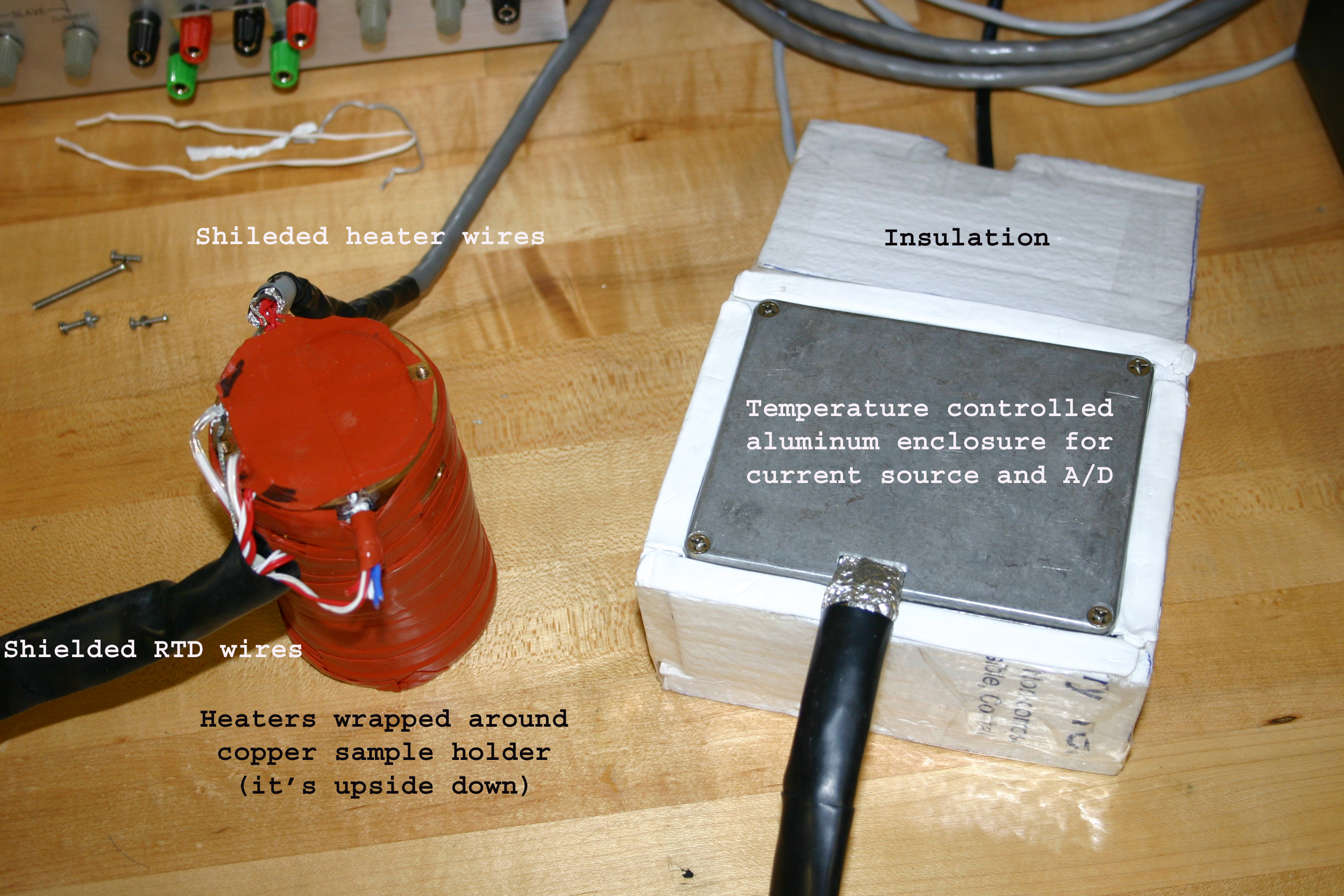
Light scattering is used to measure the relaxation time of polymer chains. The time scale for a measurement is long enough that a temperature gradient across the sample could cause convection and effect the measurement. Our goal was to keep the ends of the sample holder stable to within 0.1C. Copper was used because of its high thermal conductivity. The sample is about 0.5 cubic centimeters and the cylindrical sample holder is about six inches long. We used three heaters on the sample holder (one on the bottom and two on the sides - upper and lower). Each heater had a RTD in close proximity and there was a RTD placed directly under the sample chamber. Each heater is controlled such that the RTD directly under that heater is brought to the desired temperature.
We found the controller worked well over a range of 30-140C. The sample RTD (in the center) always read slightly higher than the heater RTDs (closer to the outside). The middle heater RTD also read higher than the ends. Because of this the middle heater only ran while increasing the temperature and was off while at a constant temperature. I think this is due to the shape of the copper cylinder, where the insulation was placed, and the size of the various heaters and their placement. From 140-160C the bottom heater couldn't supply enough power to keep the bottom of the sample holder at the desired temperature. 150C was the limit for the heaters used but the platinum RTDs could go much higher. Note: The RTD's had an initial accuracy of 0.1C but we calibrated them to around 0.01C.
Solution:
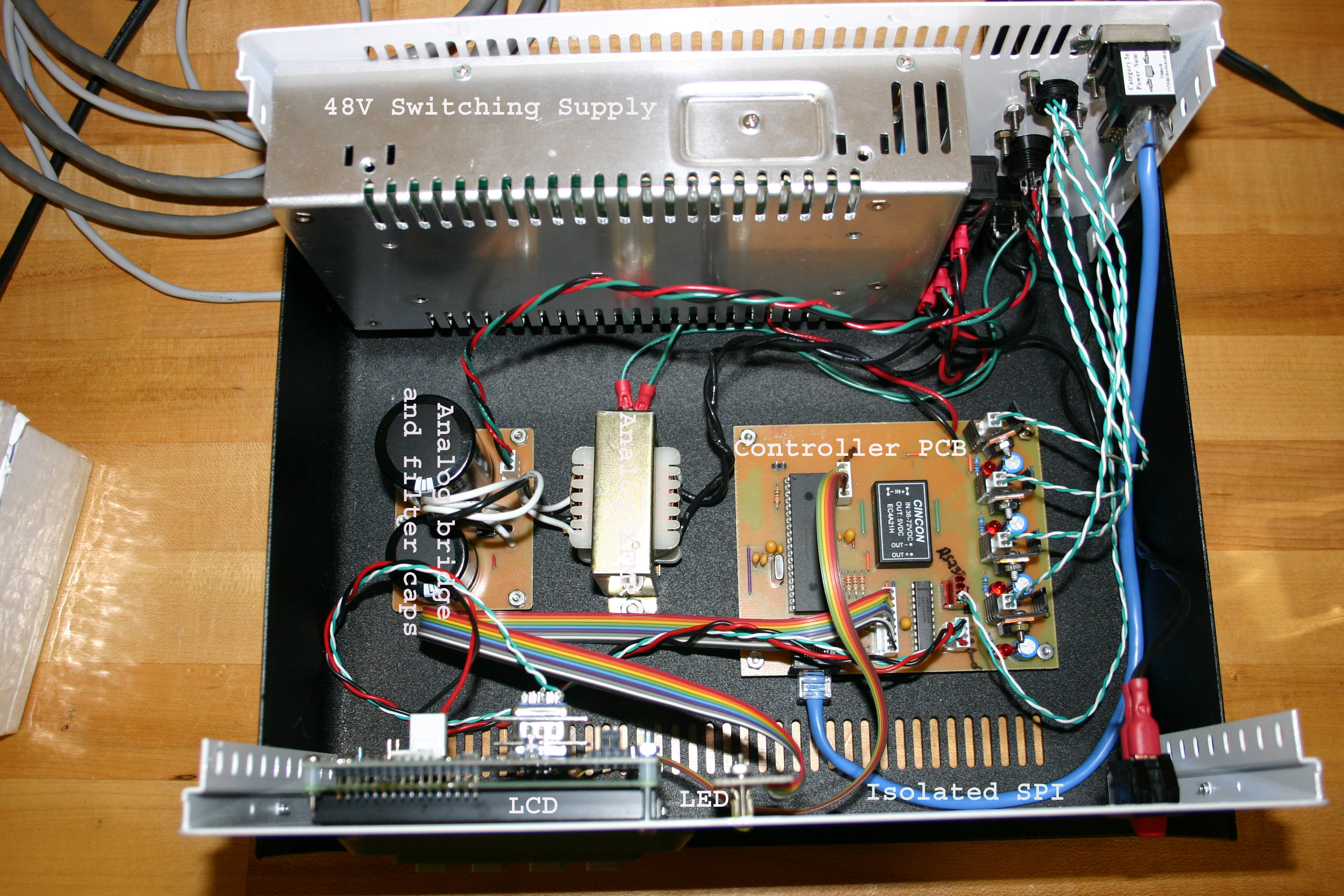
The circuit is composed of two sections (A low noise section to measure the temperature and a digital section to control the heaters and run the display). The two sections are optically isolated so noise from the digital section doesn't affect the low noise section.
Low noise section: (Refer to the Low Noise A/D Schematic)
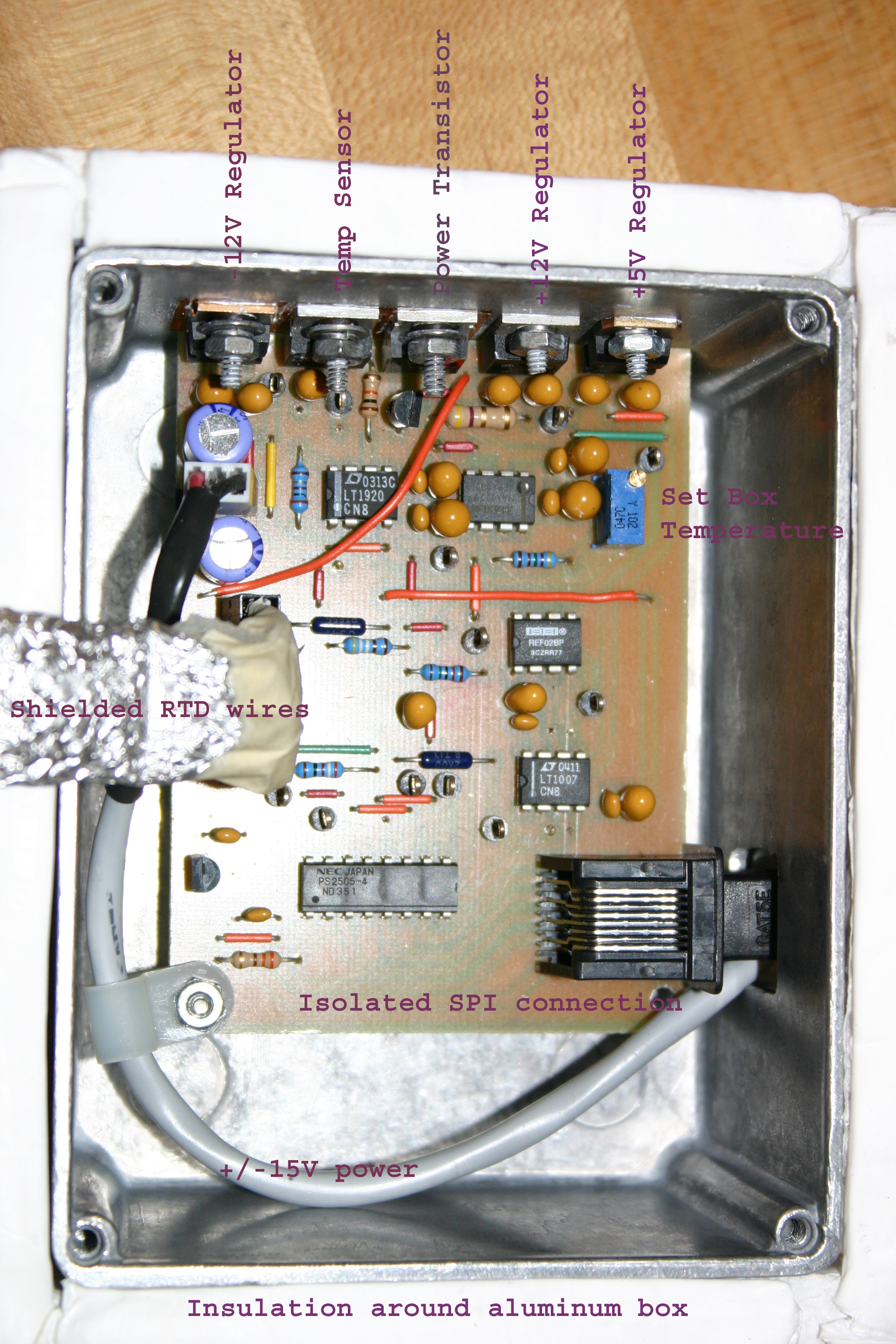
The REF02 and LT1007 form a constant current source that is stable with temperature. The current is set by the 20K resistor (5V/20K = 0.25mA). The current is sent through four platinum RTDs and a reference resistor. All RTDs are in series and have a four wire connection (two wires for the current and two wires to measure the voltage). A differential A/D (LTC2418) is used to measure the voltage drop across each RTD. The reference voltage for the A/D is set by a resistor in series with the RTDs so it's not sensitive to variations in the current source (it's ratiometric). The circuit is placed in an aluminum enclosure that's insulated and temperature controlled (about five degrees above room temperature). The enclosure temperature is also measured with the A/D and is stable to better than 0.1C. This temperature stability combined with low drift components and ratiometric operation makes the circuit very stable.
The enclosure temperature is measured using a LM35 (10mV/C) temperature sensor. The MAX6225 provides a 2.5V reference that is stable with temperature. A trim pot divides down the 2.5V to the desired temperature (10mV/C). The difference is amplified (LT1920) and used to drive a power transistor (TIP102). The Vce of the transistor is about 15V so as the temperature difference decreases the current in the transistor decreases and the heat dissipated decreases. The transistor and temperature sensor are bolted to the aluminum enclosure in close proximity to each other. The 2N3904 transistor and 4.7ohm resistor are used to limit the current in the power transistor while the box is warming up.
All clock and data lines from the A/D are optically isolated to minimize noise pickup. To keep the clock edges clean (and since the sample rate was low) data was clocked out of the A/D at about 1KHz. Note: The aluminum enclosure is tied to the circuit ground. All RTD wires are shielded and tied to this same ground. This floating ground is isolated from the digital ground and earth ground. When this ground was tied to digital ground or earth ground the noise increased. A separate linear supply powers this circuit to help isolate it from the noisy switching supply.
Digital section: (Refer to the Controller Schematic)
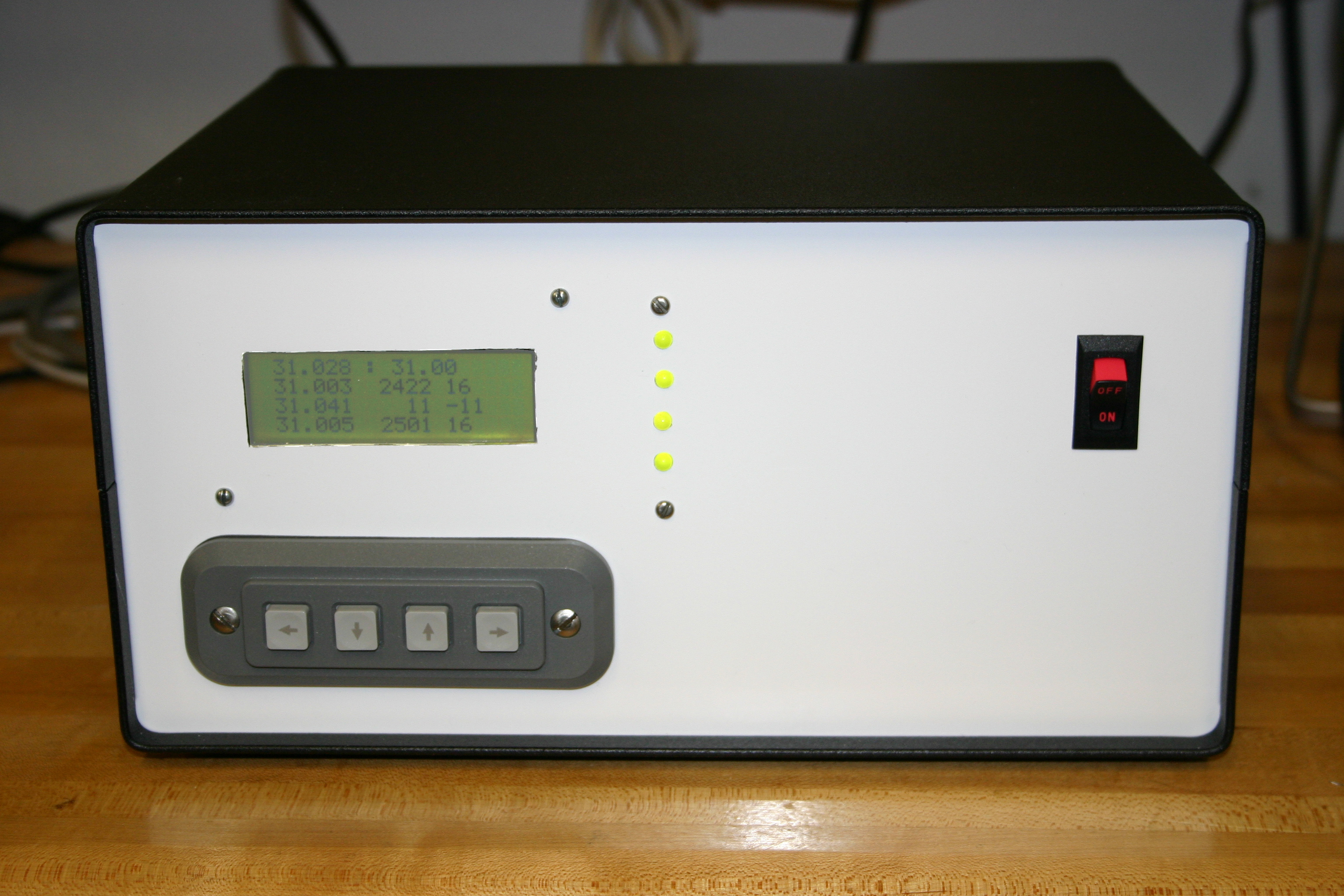
The digital section is controlled by a PIC16F877 microcontroller. It cycles through the A/D channels reading the temperatures, comparing them to the set point, and driving the heaters. The micro also reads the keypad and controls the LCD and LEDs. There are bi-color LEDs to let the user know (from a distance) if the sample has reached the desired temperature. There is one LED for each area being controlled. The LED is Red if (dT>1C), Yellow if (1C=>dT>0.05C), and Green if (dT<=0.05C). Note: To display yellow, red and green are on at the same time. The LCD displays the temperature of each RTD, the set point, and some debug info. A PI (proportional integral) controller was written and the P & I error terms for each heater are sent to the LCD. This aided in determining the proper gain settings for the control loop.
The micro controls the heaters by adjusting the how long each heater is on (i.e. its duty cycle). While ramping from a low temperature to a high temperature all heaters are on. Once near the correct temperature the heaters don't need to be driven as hard to maintain the temperature. The code was written to minimize switching transients. When one heater turns off the next heater turns on and so on in sequence. The total power supplied is the same but the peak power is lower. This is easier on the power supply and causes less switching noise than turning on all the heaters at the same time. The PWM for the heaters runs at about 4Hz. The sample rate for the A/D is also about 4Hz (taking about a second to read all four RTDs).
The heaters are switched on and off using a power FET (IRL2910). This FET works well with a 5V drive and has a low on resistance. The wires from the controller to the heaters are twisted and shielded (to the controllers ground) to minimize radiated noise.
The heaters run off a 48VDC switching supply while the micro uses a DC/DC converter to step the 48V down to 5V. The MAX233 converts 0-5V TTL to +/- 10V RS232 for the serial LCD. A DB9 serial output is also provided so that the temperatures can be logged on a computer. The keypad controls simple menu functions that allow the user to set the desired temperature or to monitor the current temperatures.