Auto Fill Circuit for Laser Cooling Loop (W/Ethernet Data Logging)
Overview and problem description:
In the physics building we have lots of water cooled equipment (Ex: gas lasers, vacuum pumps, an X-RAY source, etc). Pipes run the length of the building allowing researchers in any lab access to a stable supply of chilled water. The cooling loop is a closed system and water is slowly lost do to imperfect seals, installing new equipment, etc. As water is lost the pressure drops. If the pressure gets low enough equipment has to be shut down to prevent overheating. Similarly, if the pressure gets too high, some of the equipment has safety valves that will open to prevent damage (but when open, spill the excess water on the floor). Both scenarios have occurred while manually adding water (or forgetting to add water). Note: Because the rate at which water needs to be added to the system is so low a standard pressure regulator didnt work (the flow rate was almost zero).
Auto-fill circuit (the solution):
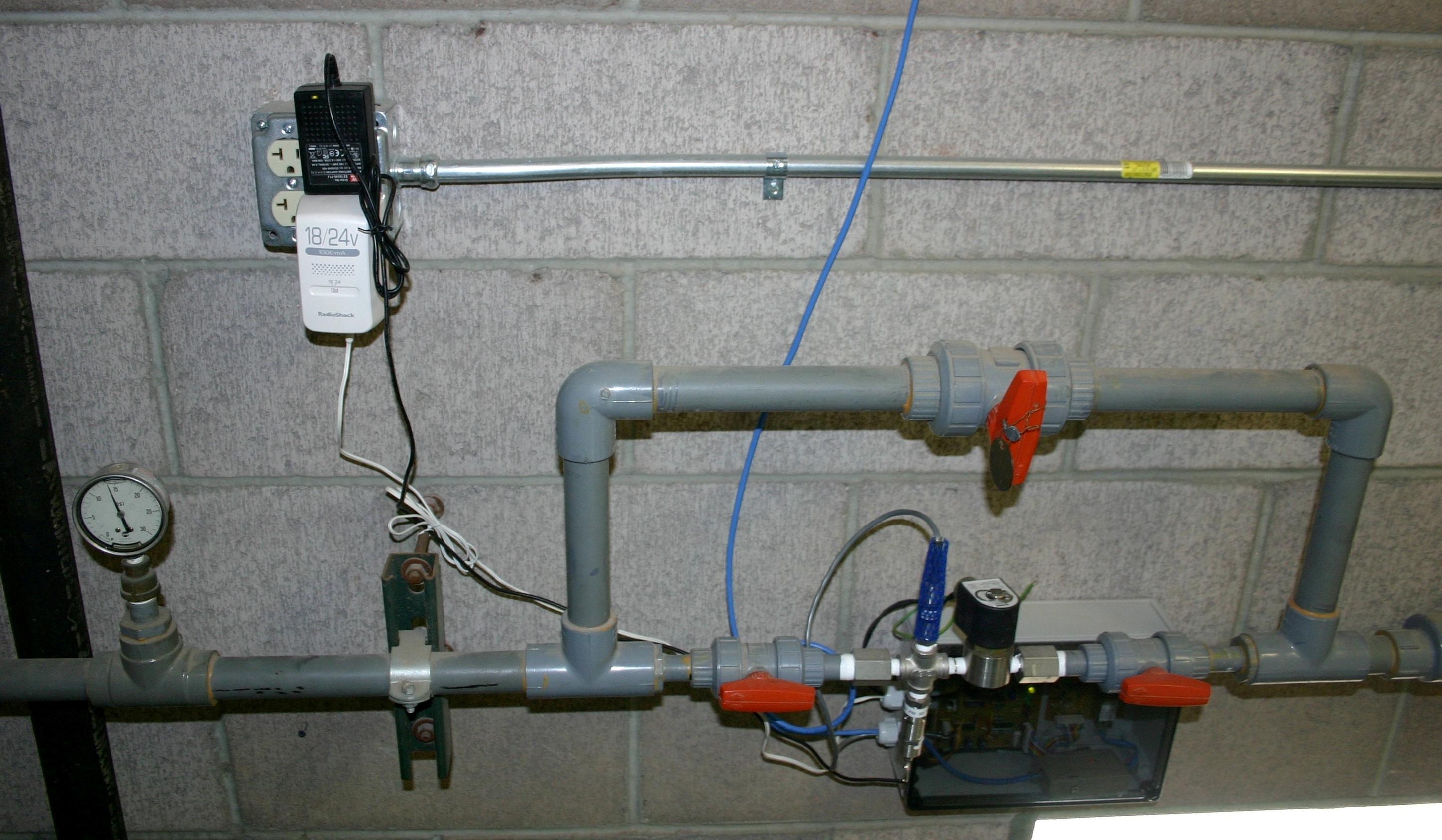
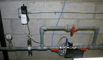
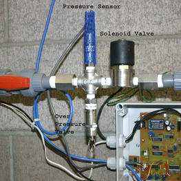
We decided to take the human element out of the equation by replacing the ineffective pressure regulator with a solenoid valve, pressure sensor, overpressure release valve, and a control circuit. Note: This overpressure release valve is in the out-building that houses the chiller and has a sloped floor with a drain. If the release valve dumps any water it water will go down the drain instead of on the lab floor. There are shut-off valves on either side of the auto-fill system for easy installation and testing. The manual bypass valve was left in place just incase a lot of water needed to be added quickly.
Circuit description:
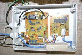
It was decided that the auto-fill circuit shouldnt use special parts (i.e. code on a microcontroller). That way the circuit could be repaired by anyone with available parts. I did use a microcontroller for Ethernet based data logging of the pressure but the auto-fill circuit is separate and works without the pressure logging feature.
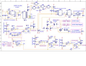
For safety the solenoid valve should never be open for very long or very often. Its just supposed to add small amounts of water to make up for leakage. A 555 timer (U8) and 4040 counter (U7) are used to control when the pressure is checked. It outputs a square wave with a user selectable frequency (jumper on PCB). The NAND gates (U5) are configured to produce a short pulse on each rising edge. The pressure is checked at the beginning of each of these pulses (currently jumpered for about every 30 minutes).
A potentiometer (R24) sets the desired pressure. That voltage is compared to the voltage from the pressure sensor. If the pressure is less than the desired pressure the comparator output (U10D) will be high. If the comparator output is high when the NAND gate pulse arrives, the on-shot (U6A) produces a user adjustable pulse. This pulse drives a transistor which drives a solid state relay which opens the solenoid valve. The valve on time (controlled by R4) is currently about 20 seconds.
The op-amps (U9) are configured as voltage followers to buffer the output of the pressure sensor and the potentiometers. The feedback resistors on the comparators provide about 0.8 psi of hysteresis (i.e. Water wont be added unless the pressure drops 0.4 psi below the set point, and will keep adding water until 0.4 psi above the set point). The pressure sensor output was low pass filtered to remove large pressure fluctuations caused by the pumps. A time constant of about 20 seconds (set by R32, C20, & C21) seemed to smooth the fluctuations to about 0.1 psi.
There are two alarm outputs if the pressure gets too high or too low. Trim pots (R27 & R21) set the upper and lower limit. Comparators compare alarm limits to the voltage from the pressure sensor and the comparator outputs go low (turning on LEDs) when the alarm limits have been exceeded.
A 24VAC wall adapter was used for power (mainly for the 24VAC valve). The 24VAC was rectified and filtered to get DC power. A DC/DC converter stepped the voltage down to 5V for the control circuit. A 3.3V low dropout regulator was also added for the Ethernet monitoring PCB (XPORT PIC uP).
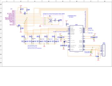
Ethernet pressure monitoring:
The Ethernet connection is based on an XPORT form Lantronics. Basically it lets you use a serial port to send things over Ethernet. A PIC microcontroller with an A/D converter digitizes the pressure, the pressure set point, the high and low pressure alarm points and the supply voltage (since everything is ratio-metric). Every time water is added to the system or there is a high or low pressure alarm it sends an email so there is a record of when something happened and how often water was added to the system. Resistive voltage dividers were used to drop all the voltages from the control circuit (0-5V) to a max of 3.3V.
Note: I found dealing with Lantronics customer support lacking. To get useful informaiton they want you to sign a non-disclosure agreement. I feel this is a ridiculous requirement and refused. Luckily, others have posted sample java code that allows the serial port on the XPORT to communicate with a text window on a web browser. This allowed me to send a text string with the pressure and setpoints over the network to be logged in a browser window. I cut & paste the text daily & clicked refresh on the browser to clear the old data. Not elegant but functional. I also found the triggering of emails to be inconsistent (either by toggling a pin or sending special ASCII codes). The emails would be sent when triggered for a while but days later the XPORT wouldnt send emails even though repeatedly being triggered. The data logging would continue so I know the XPORT is awake and the network connection is good.
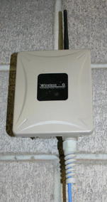
I used a wireless bridge (EOC-3220-EXT) to connect the network to the outbuilding. I probably should have got the bridge with the internal directional antenna. Instead I got the EXT one used a couple of antennas from Linx Technologies (ANT-2.4-CW-RCTA-RP, $6.50 each). The bridge was set as an access point and the other (the XPORT side) was set for MAC cloning. I couldnt get the encryption to work but then I dont know what Im doing when it comes to network stuff. This project also made me realize that knowing oldschool C, assembly, basic, etc doesnt help much when it comes to understanding object oriented Java code.
Pieces Parts:
We wanted to keep the low pressure side of the cooling loop at around 14 psi. I chose a pressure sensor (US331-000005-030PG from MSI) with a range of 0-30 psi (but can handle 90 psi without damage). It runs off 5V and has an amplified ratio-metric output from 0.5-4.5V. I chose a solenoid valve that is rated at 150 psi, has a Cv factor of 0.5 (reasonable flow rate), and is normally closed when not energized (add water only when energized - for safety). The valve runs off of 24VAC and draws 0.7A. Various couplers and adapters were used to plumb everything together. Note: Everything had to be plastic or stainless steel because the cooling loop uses deionized (DI) water.
C Code for PIC16F877
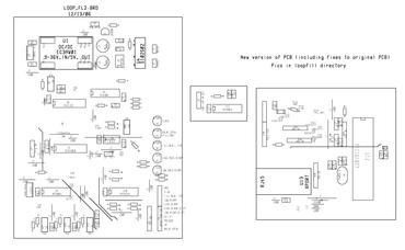
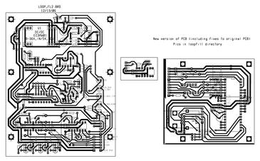
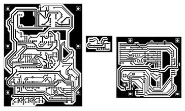
The board layout is below. The PDF files should print 1:1 for making the PCB.